

Introduction
As a kind of special construction method, grouting has many advantages, such as low cost, high efficiency, wide application range and simple operation, etc. After years of theoretical research and engineering practice exploration, grouting method has grown into one of the most effective means to control tunnel and underground engineering geological disasters [1-3].
Among them, the split grouting is the soil splits to form cracks under the action of slurry pressure, and the slurry fills the cracks and continues to split the soil around under the action of pressure, thus forming split slurry veins. Split grouting is an effective means to strengthen the poor geological body such as hard plastic clay, weathered rock and broken zone, and has been widely used in building foundation, subway tunnel, mine roadway and water conservancy and other projects [4-7].
In practical grouting engineering, the reasonable determination of split grouting parameters is the premise of ensuring the grouting effect, and the determination of grouting parameters depends on the correct guidance of grouting theory. At present, many scholars have conducted numerous studies on the split grouting of soil.
In experimental research, Yun et al. [8] carried out simulation tests of splitting grouting for sand samples under different conditions, obtained the corresponding splitting pressure, and proposed a prediction model of splitting pressure. Bezuijen et al. [9] carried out a model test of splitting path transfer in sand layer. Based on slurry separation and scanning electron microscopy, the splitting path transfer characteristics were obtained and a splitting path propagation model was established. Li and Zhang et al. [10-13] designed a large proportion splitting grouting model test device to simulate the splitting grouting process in fault fracture zone. Combined with the characteristics of soil splitting pressure changes, the splitting path propagation process was proposed based on slurry diffusion form conversion, primary and secondary splitting path saturation, new splitting path formation and subsequent splitting region saturation. Li et al. [14] carried out a three-dimensional grouting simulation test of segmented split grouting in a soft, obtained the spatial distribution characteristics of grouting veins, revealed the mechanical mechanism of segmented split grouting reinforcement. Niu et al. [15] conducted a 3D simulated grouting test on the soil, following which the diffusion rule of slurry in the filling medium and the reinforcement mechanism of split grouting were analyzed according to the properties and distribution characteristics of grouting veins after grouting reinforcement. In a theoretical study, Zhang et al. [16] deduced the relationship between the thickness of round cake split pulpy veins in sand texture layer and the grout pressure and grout diffusion radius. Based on the hyperbolic soil compression model. Zhang et al. [17] studied the relationship between the splitting thickness of round cake split slurry veins of clay and the slurry pressure and diffusion radius. Besides, some researchers established a split grouting diffusion equation for different constitutive models, and a relationship between the grouting pressure or slurry viscosity and the diffusion radius of the slurry [18-21].
The above theories all assume that one grouting is carried out. In the actual grouting project, multiple grouting is required to ensure the reinforcement effect. There is less research on the diffusion mechanism of multi sequence split grouting. In addition, the existing split grouting theory has less consideration on the loss of grouting pressure along the way, that is, the gradual pressure at the grouting hole corresponding to the thickness of grout vein at different diffusion radius is different.
In order to solve the above problems, based on the Newtonian fluid constitutive model, this paper establishes a soil compression model to simplify the dynamic development process of the cleavage grouting vein, simplifies the multi sequence cleavage grouting diffusion process into a plane radiation circle, and takes into account the loss of grouting pressure along the path, derives the control equations of the multi sequence cleavage grouting with controllable direction and distance, and obtains the calculation method of the corresponding grouting time, finally, the model test of split grouting is carried out to verify the rationality of the theoretical model.
Compression Characteristics of Rock and Soil Mass
The soil mass is composed of medium particles and air or water in the gap between particles. During the compression process, the gap between particles will be reduced, and the air or water in the gap will be squeezed out. The compression properties of different rock and soil masses can be expressed by the compression curves e-p or ε-p, where e is the porosity ratio, p is the pressure, and ε is the compressive strain. The soil compression curves with e as the vertical coordinate and p or lgp as the horizontal coordinate can be obtained through the consolidation test under the condition of full measurement limit. Therefore, it can be obtained according to the known e-p mathematical expression ε-p mathematical expression, using ε-p mathematical model to express the process of rock and soil mass being compressed. The ε-p curve is shown in Fig. 1. The compressive strain increases with the increase of pressure, but the increment is smaller and smaller. In this paper, the parabolic model is used to represent the nonlinear compression process of rock and soil mass compressed by grout veins, and the ε-p The mathematical model expression is:
Where A, B and C are coefficients to be determined.
According to the derivation in the literature [16], the nonlinear compression strain and stress mathematical model of rock and soil mass compressed by grout vein can be obtained:
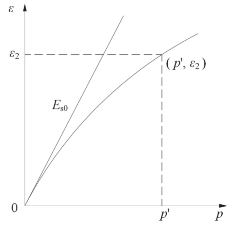
Where, Es0 is the initial compression modulus of the injected soil mass, ε2 is the corresponding compressive strain of the soil mass when the compressive stress of the compressed soil mass rises to p’. Compared with the existing mathematical model of soil compression, this formula can describe the compressive stress-strain relationship in a higher-pressure range (0-2 MPa), and has stronger applicability for grouting engineering.
Key Pressure in Slurry Diffusion
Model Assumptions
Under the initial crustal stress condition, the grout of the first sequence grouting spreads horizontally from the grout outlet to the surroundings. The grout vein splitting diffusion model is shown in Fig. 2a), which shows the longitudinal profile of the round cake grout vein. The grout vein thickness is b, and the horizontal plane passing through the grouting hole is taken as the symmetrical plane. With the increase of the grout vein diffusion half diameter, the grout vein thickness gradually decreases. At the farthest diffusion distance of rmax1, the grout vein thickness decreases to 0. However, in the process of pre grouting, the grout vein compresses the upper and lower soil mass, which makes the vertical crustal stress gradually increase. For different required grout diffusion radii, different grouting pressures need to be set, so there is a rmax0 that can increase the vertical crustal stress near the grouting hole, that is, the small principal stress of rock and soil mass to be equal to the large principal stress. When the preset rmax is greater than rmax0, the direction of the large and small principal stresses changes, as shown in Fig. 2b).
In order to study the dynamic development process of the prophase and anaphase cleavage plasma veins, the following assumptions are made:
(1) Before the first grouting, the initial state of the rock and soil medium is: the direction of the large principal stress σ1 is horizontal, and the direction of the small principal stress σ3 is vertical. After the first sequence of grouting, the horizontal grout vein only compresses the upper and lower rock and soil mass, and the horizontal principal stress changes little, so it is assumed that the horizontal principal stress is still σ1. The vertical principal stress becomes σ3’, and the changed vertical principal stress is greater than the horizontal principal stress, namely σ3’ becomes the major principal stress;
(2) Under the condition of controllable pressure, the pressure rises rapidly to the splitting pressure, regardless of the influence of the initial grout bubble on the splitting process, the grout diffuses radially and symmetrically from the grouting hole to the periphery, and the width of the splitting path of the first grouting grout diffuses horizontally. After the first sequence grouting is completed, the secondary grouting will be carried out after the ground stress recovers and becomes stable. Due to the change in the direction of major and minor principal stresses, during the subsequent splitting process, the grout vein will spread in a round cake shape along the vertical direction from the grouting hole, and the width of the splitting path will decrease along the diffusion direction, which is the largest at the grouting hole and the smallest at the splitting tip;
(3) The slurry is homogeneous, isotropic, and incompressible Newtonian fluid, and its flow and diffusion mode is laminar flow. During the flow process, the influence of the gravity factor of the slurry itself on the slurry diffusion process is ignored. The speed on the center line of the circular cake interface is the largest, the closer to the rock and soil wall, the smaller the speed is, and the speed on the wall is zero;
Fig. 2.
Propagation model of fracture grouting: Schemes follow another format. If there are multiple panels, they should be listed as: a) Splitting diffusion model of grout vein for preceding grouting; b) Splitting diffusion model of grout vein for subsequent grouting.
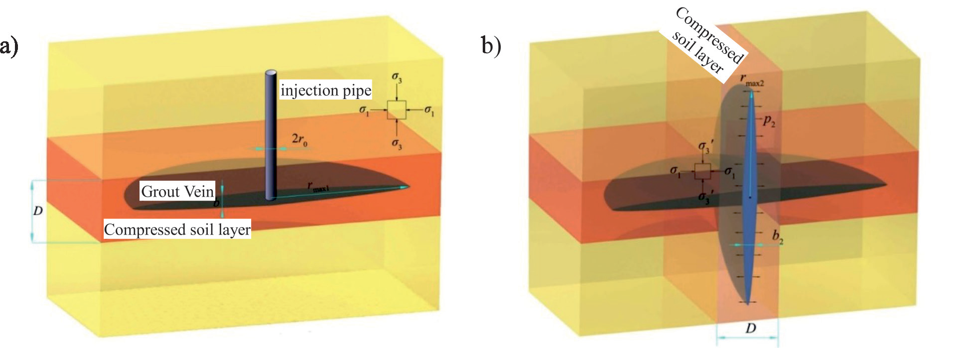
(4) The condition for stopping the expansion of the grout pulse is that the grouting is stopped or the grout pressure at the tip of the round cake of the grout pulse decreases below the splitting pressure. Respectively, during the first sequence grouting, the slurry pressure at the tip of the round cake splitting slurry vein decreases to a small principal stress σ3. During subsequent grouting, the slurry pressure at the tip of round cake splitting grout vein decreases to a small principal stress σ1.
(5) The pressure p of the first grouting slurry compresses the surrounding soil mass, causing the rock and soil mass within the range D to compress and deform ε-p If the p relation conforms to formula (2), the thickness expression of the pulp vein is:
The subsequent grout pressure p2 compresses the surrounding soil, which makes the rock and soil mass in the range D undergoes compression deformation. However, since the horizontal grouting pulse of the first sequence grouting only affects the stress of the rock mass in the range D, and the extension length of the vertical split grouting pulse is much longer than that of D, the influence of the first sequence grouting on the ε-p relationship of the rock mass on both sides of the second sequence grouting pulse is not considered, that is, the values of A and B are unchanged.
(6) The loss of secondary pulpy veins and other grout caused by uneven filling and unequal grout is not considered;
(7) Constant grouting pressure can be achieved by adjusting the grout flow rate.
Determination of Splitting Pressure
When the grout cannot penetrate into the geotechnical pores, it will accumulate into slurry bubbles at the grouting outlet, and when the pressure increases to a certain extent, the grout will split the geotechnical mass to form slurry veins and spread around. The grouting pressure for splitting is called split pressure or split pressure, and the occurrence and development mechanism of split grouting is obtained based on the expansion and research of the hydraulic splitting principle. When the grouting pressure is greater than the sum of the minimum principal stress in the reinforcement zone and the tensile strength of rock and soil mass, split grouting will occur.
The damage form of grout splitting to rock and soil mass is tensile failure. If there are original cracks or weak surfaces at the grouting outlet, grout will preferential split the weak area. If there is no weak zone, the research method of hydraulic splitting is used for reference, as shown in Fig. 3. The rock and soil mass are assumed as uniform medium and isotropy, the vertical direction around the grouting outlet is the minimum principal stress σ3 the horizontal stress is the maximum principal stress σ3, the grouting pressure is p, the radius of the grouting hole is r0, and the tensile stress is negative and the compressive stress is positive. The included angle between the pulp bubble and the X axis of the coordinate system is θ, the stress state of any point A whose distance from the center of the pulp bubble r is:
(4)
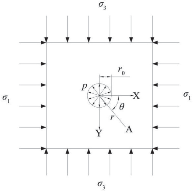
Where σr is radial stress, σθ is tangential stress and τrθ is shear stress. As the radius r increases, the slurry pressure gradually decreases, and the stress state at r = r0 is:
According to Equation (5), when the grouting pressure is large enough, it is negative, and when θ = kπ, (k = 0, 1, 2.) When cos2θ = 1, the absolute value of tensile stress |σθ| is the maximum, and the stress state at this position is:
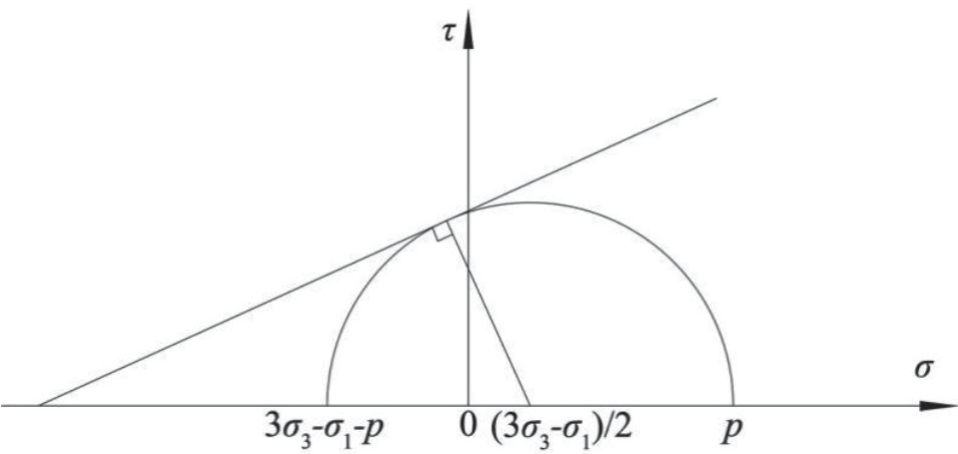
When θ = kπ, the tensile stress reaches its maximum value in the horizontal direction 3σ3-σ1-p, as shown in Fig. 4. If the absolute value of the horizontal tensile stress |σθ| is greater than the maximum tensile strength of the medium in the region σm, the rock and soil mass will be split in the horizontal direction, that is, splitting slurry veins will occur when the grouting pressure p increases to 3σ3-σ1-σm.
According to the Mohr-Coulomb criterion:
Where, τ is the shear stress, c is the cohesive force of rock and soil materials, σ is the normal stress acting on the plane, φ is the Angle of internal friction of rock and soil materials. Fig. 4 shows the position of stress Mohr circle at the grouting outlet when the rock and soil mass are about to be destroyed, which is tangent to the tensile strength line. Radial stress σr and tangential stress σθ is the maximum and minimum principal stresses respectively. Any point on Mohr’s circle is an inclined plane α parallel to the minimum principal stress. The horizontal coordinate is the normal stress on the inclined plane, and the vertical coordinate is the shear stress on the inclined plane.
The center of a Mohr’s circle is
Combined with (6), (7) and (8), we can get:
The grouting pressure obtained by Equation (9) is the splitting pressure of the rock and the soil medium, which is related to the cohesion of the rock and soil mass, the Angle of internal friction and the major principal stress, and the direction is parallel to the major principal stress direction.
Determination of Expansion Pressure
In the process of slurry diffusion, the tip of the round cake pulse keeps splitting the rock mass, causing the pulse to expand around. The splitting pressure at the tip is different from the initial splitting pressure, which is called the pulse spreading pressure pk. According to the fracture spreading theory, the pressure of the pulse spreading can be expressed as follows:
Where, r is the diffusion radius of slurry; r0 is the radius of grouting hole; and G(r/r0) and F(r/r0) is the coefficient of r/r0, and when r is much larger than r0, G(r/r0) = F(r/r0) = 1; K1 is the fissure related strength factor.
Since r is much larger than r0 in practical engineering, and πr is much larger than K1, the pulse expansion pressure of round cake is pk≤σ3, and when the tip pressure p≤σ3, the pulse will not expand.
Pressure Control Method in Split Grouting Process
First Sequence Horizontal Splitting Diffusion
Slurry Splitting Model
The splitting process of grout in rock and soil mass needs to consider the compression characteristics of rock and soil mass, as well as the rheological properties of grout. The dynamic diffusion process of grout is analyzed below.
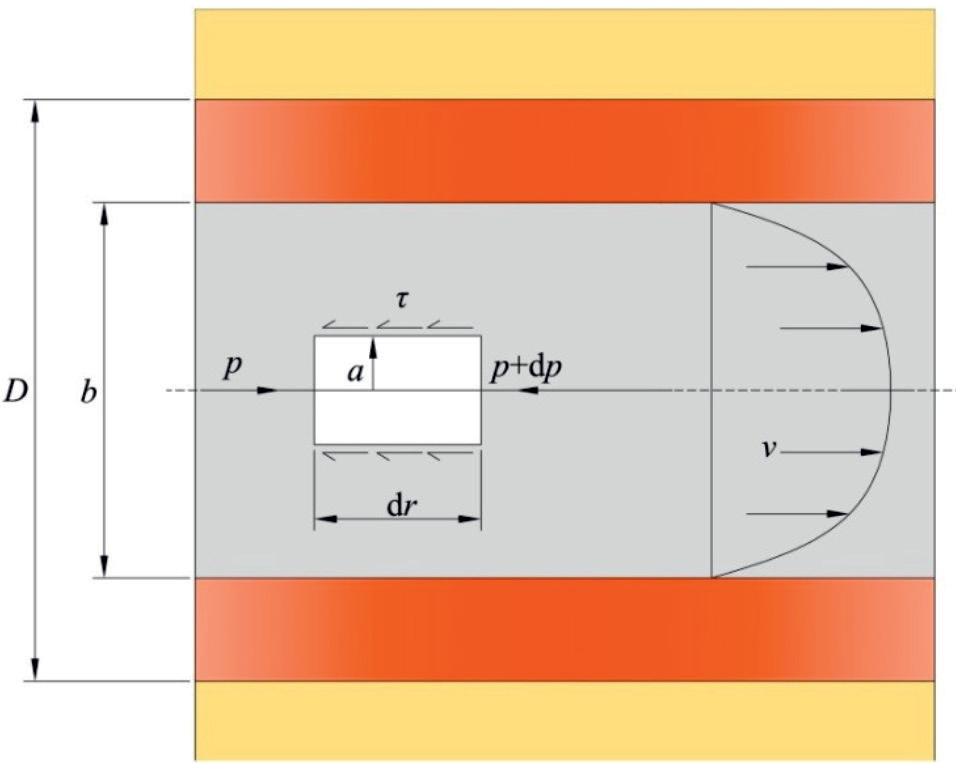
If the grout is a Newtonian fluid, the force analysis is shown in Fig. 5, and the shear stress expression is:
As shown in Fig. 5, it is assumed that the movement of grout in the crack is equivalent to the flow in a section, which starts from the grouting outlet and diverges to all sides. There is an axisymmetric grout fluid column in the section of the grout vein, and the thickness of the grout fluid column at the diffusion radius of r is b1. A grout fluid column at any axis with the length of dr and the radius of a less than b1/2 is taken, and the mass of the fluid colup1 is the pressure exerted by the grout, τ is the shear stress exerted by the grout fluid column, the grout density is ρ, and its force equation is:
After transformation, we can get:
The above formula shows that the shear stress τ. The value of is proportional to the distance from the central axis, so the shear stress near the centerline of the pipe τ is very small. Should be equal to zero here. Therefore, for Bingham fluid in this section, there is a cylinder with radius a0, and the shear stress of fluid in the cylinder τ shear stress less than radius a0 of the cylinder τ0, that is, the fluid is relatively static within radius a0 and the overall velocity is the same as v0, while at a0 ≤ a ≤ b1/2, the fluid velocity is different, and it can be obtained that:
According to the force balance formula:
By integrating equation (15), we can get:
In the formula, c is the integral constant. Since the velocity v at a = b1/2 is 0, it can be obtained that the integral constant c is:
So, the expression of velocity v is:
As with Bingham fluids, the average velocity can be obtained from the total flows of the pulp:
After sorting out formula (19), we get:
During the diffusion process of round cake slurry vein, the grout flow through the section at any radius r1 is equal to the grouting flow, and the grouting flow Q1 has the following relationship with the slurry speed v̅ :
By combining (20) and (21), it can be obtained that the pressure gradient of Newtonian fluid slurry pulse is:
By combining (22) and (3) can obtain:
After integrating the above equation, we can get:
Where c1 is the integral constant, when r = rmax1, p1 = σ3. Substituting the boundary conditions into the above equation, we can get:
The relation between the diffusion radius of Newtonian fluid slurry pulse and the slurry pressure can be obtained by taking (25) into (24):
According to the relationship between the diffusion radius and the grout pressure in the above formula, the grout pressure at different diffusion radii can also be obtained. When r1 = r0 (r0 is the radius of the grouting pipe) is known, the grout pressure is equal to the pressure at the grouting pipe orifice, so the relationship between the maximum diffusion radius rmax1 and the grouting pipe orifice pressure p01 can be obtained:
(27)
Considering the loss hf along the grouting pressure, the relationship between the pump outlet pressure and the grouting pipe orifice pressure is as follows:
Where, pset is the output pressure of grouting pump, Pa; hf is the loss along the way, m; ρ is the medium density, kg/m3. In conclusion, the formula of grouting pump outlet pressure of Newtonian fluid grout can be obtained according to the set grout diffusion radius:
(29)
Put the above equation into polynomial of degree 5:
(30)
For a given rmax1, it is unrealistic to require the 5th degree polynomial of solution (30). In this paper, the corresponding relationship between grouting pressure and diffusion radius is obtained through reverse fitting. With the increase of grouting pressure, the diffusion radius of grout, rmax1, gradually increases. The two are positively correlated and one-to-one corresponding. Therefore, in order to obtain the grouting pressure corresponding to different diffusion radius rmax1, first find the slurry diffusion radius under different grouting pressure according to Formula (27).
The initial value of grouting pressure is set as ph0, and the corresponding slurry diffusion radius is rh0. The initial value ph0 is assigned as the splitting pressure
(31)
Since the amplitude and measurement error of the output pressure of the grouting pump are far greater than 10 kPa, the approximate value of the grouting pressure setting value can be obtained as follows:
Calculation Method of Grouting Time
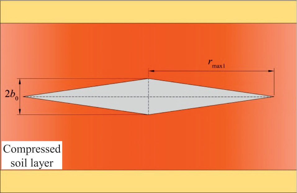
In the actual construction process, the split grout vein usually extends from several meters to more than ten meters, and the grout vein thickness is only a few millimeters. The change rate of the thickness in the slender grout vein is not large. Therefore, in the process of calculating the grouting time, the grout vein thickness b1 is approximately linear, and the grout vein section can be assumed to be triangular, as shown in Fig. 6.
According to the interface of the pulp pulse, the volume of slurry consumed by the round cake pulp pulse is:
Where, V11 is the volume of round cake grout vein, and b01 is the thickness of grout vein at the grouting hole. Wherein,
According to the Q1 change curve, the total volume of grout discharged by the grouting pump is:
The total volume of grout discharged by the grouting pump is equal to the amount of grout retained in the grouting pipeline V2 plus the volume of round cake grout vein V11, so the grouting time t1 under the grouting pressure p01 when the set diffusion radius is rmax1 can be obtained according to the following formula.
A Newtonian Fluid Grout Splitting Model for Secondary Grouting
The process of secondary grouting is the same as that of prior grouting. According to the control equation of Newtonian fluid, the pressure gradient of grout vein can be obtained as follows:
The relation between diffusion radius of Newtonian fluid slurry pulse and slurry pressure is then obtained:
The relationship between the maximum diffusion radius rmax2 and grouting nozzle pressure p02:
(39)
Considering the loss hf along the grouting pressure, the relationship between the pump outlet pressure and the grouting pipe orifice pressure is as follows:
The initial value of grouting pressure is set as pv0, the corresponding grout diffusion radius is rv0, and the initial value pv0 is assigned as the splitting pressure:
Where φ′ and c′ are the internal friction angle and cohesion near the grouting hole during secondary grouting. Calculate a diffusion radius every 10 kPa interval:
(42)
Approximate values of secondary grouting pressure setting are:
Calculation Method of Secondary Grouting Time
The volume of slurry consumed by the vertical round cake pulp pulse is:
In the formula, V12 is the volume of the round cake pulp and b02 is the thickness of the pulp at the grouting hole. Where
According to the change curve of Q2, the total volume of grout discharged by grouting pump is:
The total volume of grout discharged by the grouting pump is equal to the grout reserve V2 in the grouting line and the volume V12 of round cake pulp liquid. Therefore, when the set diffusion radius is rmax2 according to the following formula, the grouting time t2 under the grouting pressure p02 can be obtained.
Three-Dimensional Splitting Grouting Model Test
Testing Device and Materials
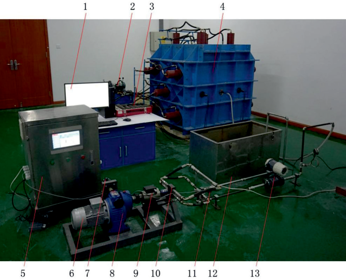
The split grouting model test system includes six parts: model frame unit, ground stress loading unit, ground stress monitoring unit, grouting unit, grouting pump monitoring unit, grouting pump control unit, etc. The model frame unit includes: model frame, grouting pipe, ground stress loading unit includes: hydraulic station, hydraulic cylinder, hydraulic tandem device, high-pressure hose, and ground stress monitoring unit includes: earth pressure cells, XL2101G static strain gauge, and computer. Grouting unit includes: SDU-0.5S-23 Wankel pump, slurry storage bucket, hand-held mixer, high-pressure pipeline. Grouting pump monitoring unit: flow sensor, pressure sensor, torque sensor. Grouting pump control unit: stepping motor, PLC control cabinet, AC motor, system layout is shown in Fig. 7.
The soil used in this test is from a soil field in Weifang. According to the results of consolidation test and shear test, the initial compression modulus Es0 of soil mass and the strain at the stress value of 2000kPa can be obtained ε2. Cohesion c, internal friction angle φ. The specific characteristics are shown in Table 1.
According to the data in Table 1 and Formula (2) and (3), the compression characteristic coefficients A.B and C of soil for test can be obtained as follows:
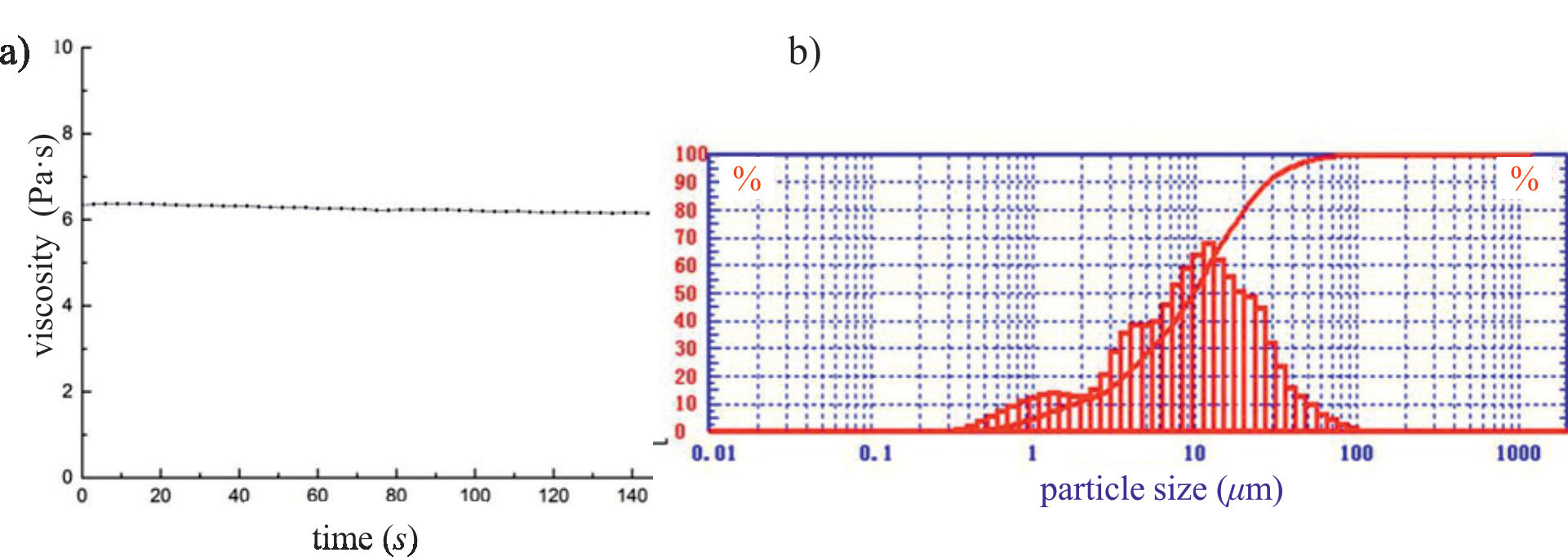
42.5R ordinary Portland cement is selected for the test. The water-cement ratio of cement slurry is 1:1. Ignoring the change of slurry viscosity with time, an SV-100 vibrating wire viscometer is used to detect the shift in cement slurry viscosity with time. A laser particle size analyzer is used to measure the particle size distribution of cement samples. The slurry viscosity and particle size distribution are shown in Fig. 8. The average viscosity of grout and the characteristic diameter of grouting material is taken as d90. The statistical results are shown in Table 2.
Fig. 7.
Model test system: 1. Computer; 2. Hydraulic station; 3. Strain gauge; 4. Model frame; 5. PLC control cabinet; 6. AC motor; 7. Stepping motor; 8. Stepless transmission; 9. Torque sensor; 10. SDU-0.5-23; 11. Pressure sensor; 12. Slurry storage tank; 13. Electromagnetic flowmeter.
Filling Soil and Place Earth Pressure Cells
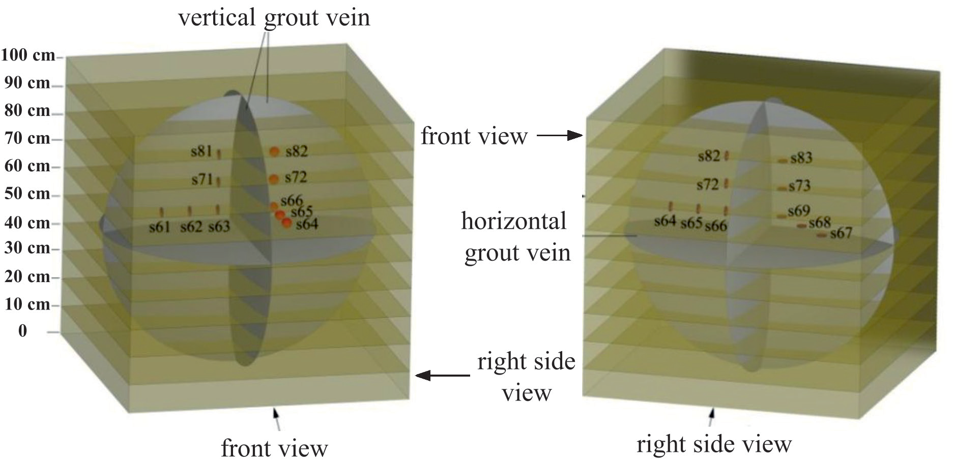
The injected soil mass model is made of a cube with a length, width and height of 100 cm. The grouting pipe is inserted vertically from the top, and the grouting outlet is located at the center of the cube. The horizontal split round cake pulse of the prior grouting occurs on the 50cm horizontal plane, as shown in Fig. 9. The vertical split round cake pulse generated during the secondary grouting is perpendicular to the horizontal round cake pulse, but the direction of the vertical round cake surface is uncertain. In this experiment, the horizontal stress is applied in two mutually perpendicular directions. Therefore, the direction of the vertical pulse is limited to the two potential directions of the front and right view. The vertical split round cake pulse generated during the secondary grouting is perpendicular to the horizontal round cake pulse, but the direction of the vertical round cake surface is uncertain. In this experiment, the horizontal stress is applied in two mutually perpendicular directions. Therefore, the direction of the vertical pulse is limited to the two potential directions of the front and right side view.
In Fig. 9, the soil mass in the model is divided into 10 layers, each of which is 10 cm. The horizontal splitting of the preceding grouting occurs in the 50 cm soil layer. In order to avoid the interference of the embedded earth pressure cells on the direction of the two circular cake veins, the arrangement of the earth pressure cells is dispersed in the space between the two possible directions of the horizontal and vertical cake veins, as follows:
A total of 15 earth pressure cells are arranged in the model, and 9 are arranged in the 60cm soil layer, namely s61, s62, s63, s64, s65, s66, s67, s68 and s69. Among them, s61, s62, s63, s64, s65 and s66 are placed vertically to monitor the horizontal ground stress. s61, s62, s63 face the right view direction, s64, s65, s66 face the face direction; Three layers, s71, s72 and s73, were arranged in the 70cm soil layer. s71 and s72 were placed vertically to monitor the horizontal ground stress, with s71 facing the right view direction and s72 facing the face direction. Also, three units, s81, s82 and s83, were placed vertically in the 80 cm soil layer to monitor the horizontal ground stress, with s81 facing the right view direction and s82 facing the face direction. Fill the injected soil medium layer by layer, and before the soil layer exceeds the height of the lead hole, all the soil pressure gauges are introduced into the model through the lead hole. The sensor data line is derived along the outer ring according to the principle of separating the pulping pulse path, and a reasonable length of the data line is reserved before burying the lead hole.
Apply Crustal Stress
The major and minor principal stresses of the split grouting model test are set as 200kPa and 100kPa respectively, and the horizontal control system and vertical control system of the hydraulic station are loaded respectively until the horizontal stress and vertical stress reach the set value. Record the stress values of earth pressure cells at s63, s71, and s81 to display the horizontal stress, and record the stress values of earth pressure cells at s69, s68, and s67 to display the vertical stress. The stress change curve is shown in Fig. 10.
Grouting Process
The grouting process is divided into two injections. Under the action of large horizontal principal stress, the first sequence grouting will cause the spread of horizontal fracturing fluid. According to the cohesion c = 27.5 kPa and internal friction angle φ = 22.83° in Table 1, large principal stress σ1 = 200kPa and small principal stress σ3 = 100kPa, it can be obtained that the splitting pressure of the pre-grouting is:
For the convenience of rounding, ph0 selects the approximate value of the splitting pressure of 100 kPa, and the influence range D is 30 cm. Due to the change of grouting flow at any time, the diffusion radius and grouting time of corresponding grouting pressure cannot be accurately obtained. According to the output performance curve of SDU-0.5S-23, the grouting flow is selected as a constant value of 5 L/min. Setting the maximum radius of slurry horizontal diffusion round cake slurry vein as 0.4 m, it can be obtained that the set value of grouting pressure is 391.59 kPa, and the estimated grouting time is 71.1 s.
Fig. 10.
Filling soil and place ground stress sensors: a) Vertical stress loading curve; b) Horizontal stress loading curve.
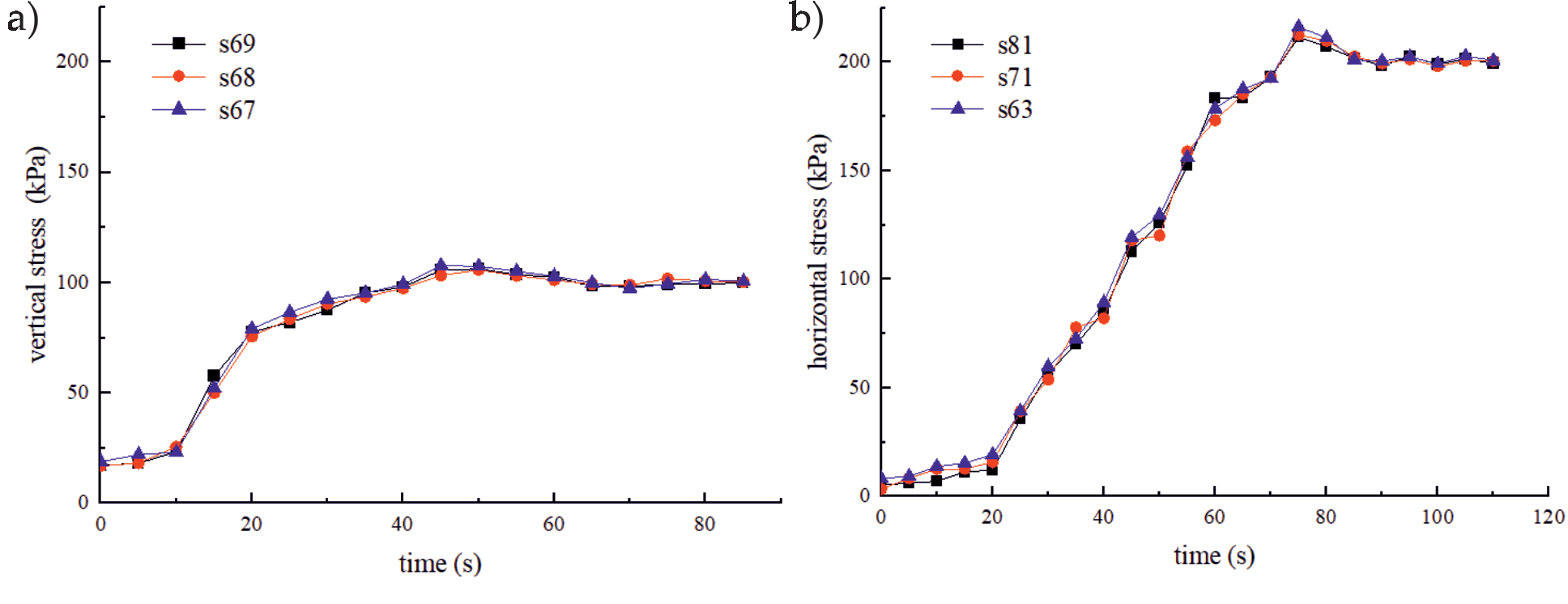
Table 3.
Parameters of grouting.
| First sequence grouting | Second grouting | |
|---|---|---|
| Set pressure (kPa) | 391.59 | 473.2 |
| Grouting time (s) | 71.1 | 55.3 |
| Diffusion radius (m) | 0.4 | 0.4 |
Since the accurate secondary grouting splitting pressure cannot be calculated in advance, the secondary splitting pressure should be greater than that of the previous grouting. The pv0 should be 150kPa, and the grouting flow should also be 6 L/min. Setting the maximum radius of slurry horizontal diffusion round cake slurry vein as 0.4 m, it can be obtained that the set value of grouting pressure is 473.2 kPa, and the estimated grouting time is 55.3 s. See Table 3 for statistics of control parameters of two injections.
Change Monitoring of Ground Stress
The initial grouting process lasted 72 s in total. The fluctuation of the ground stress during this period is shown in Fig. 11. The values monitored by the earth pressure cells s61, s62, s63, s71, and s81 that monitor the horizontal stress fluctuated around the initial ground stress of 200 kPa, and then increased slightly, indicating that the horizontal splitting grout pulse has little influence on the horizontal stress; The values monitored by the vertical earth pressure cells s67, s68, s69, s73 and s83 are gradually increased under the compression of the horizontal split grout vein. With the increase of the horizontal distance and vertical distance from the grouting hole, the response speed of the vertical crustal stress is faster, and the increase of the vertical crustal stress is larger. Finally, the vertical crustal stress monitored by s67, s68, s69, s73, and s83 are 218.45 kPa, 226.63 kPa, 241.9 kPa, 195.56 kPa, and 155.71 kPa, respectively, it can be found that the vertical crustal stress near the grouting hole has been greater than the horizontal crustal stress, and the direction of the large and small crustal stress near the grouting hole has changed, providing conditions for the vertical splitting of the secondary grouting grout.
Fig. 11.
Stress fluctuation of the first grouting: a) Horizontal stress by first grouting; b) Vertical stress by first grouting.
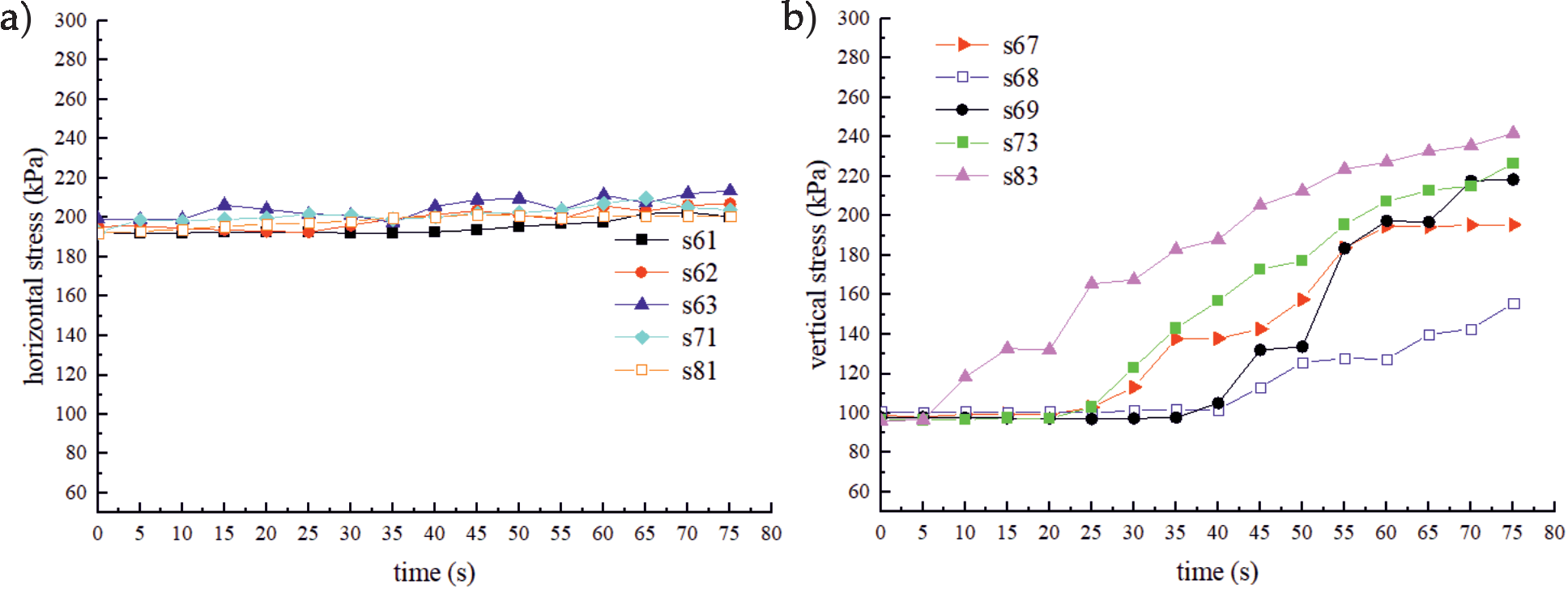
Fig. 12.
Stress fluctuation of the second grouting: a) Horizontal stress by second grouting; b) Vertical stress by second grouting.
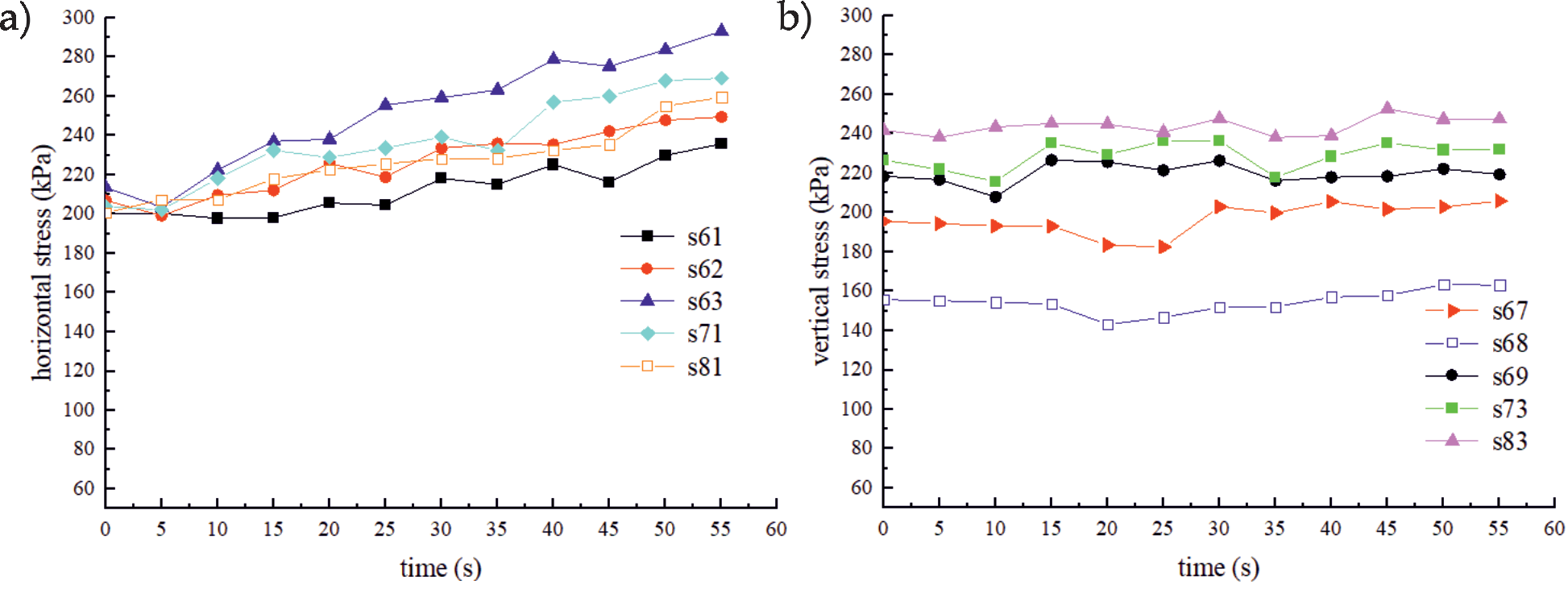
After the completion of the first sequence grouting, the model frame shall stand for 2 h, and the cement slurry shall be reconfigured for secondary grouting. The duration of secondary grouting is 55 s. As shown in Fig. 12, the data monitored by the earth pressure cells s61, s62, s63, s71, and s81 that monitor the horizontal stress starts to rise at about 200 kPa. The greater the horizontal distance and vertical distance from the grouting hole, the faster the response speed of horizontal ground stress and the greater the added vertical stress. The final vertical ground stress monitored by s61, s62, s63, s71, and s81 are 235.73 kPa, 249.52 kPa, 293.12 kPa, 269.21 kPa 259.44 kPa; The values monitored by the vertical earth pressure cells s67, s68, s69, s73 and s83 fluctuate around the initial value, and are not significantly affected by the vertical splitting grout pulse.
The earth pressure cells s64, s65, s66, s72, and s82 that monitor the horizontal stress in the front view direction are not subject to compression, and the monitored data are not significantly affected by the initial ground stress horizontal and vertical split grout veins.
Expose the Split Plasma Vein
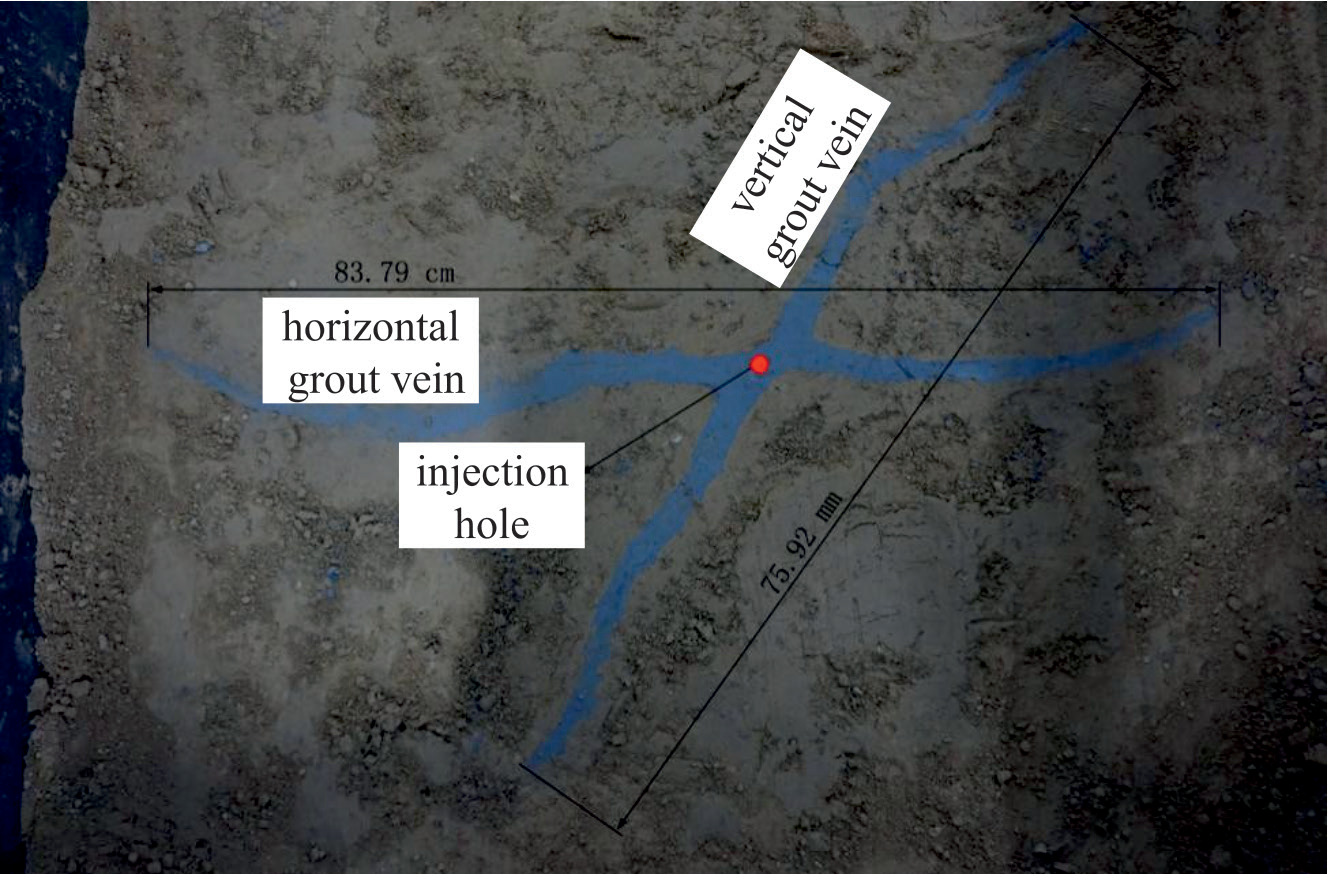
After grouting, gradually remove the grouting equipment, and facilities around the model frame, dismantle the model frame in layers, excavate and expose the split grout vein as shown in Fig. 13. The horizontal split grout vein and the vertical split grout vein can be seen. Because of the uneven soil filling in the test process, the vertical grout vein did not spread completely in the vertical direction, the diffusion diameter of the horizontal grout vein was about 83.79 mm, and the vertical grout vein was about 75.92 mm.
Conclusions
Different from the traditional grouting method and calculation conditions, based on the condition of constant grouting pressure, considering the soil compaction effect and pressure loss along the path in the multi-sequence grouting process, the slurry diffusion law and control method are studied to obtain the optimal grouting control method. The main conclusions are as follows:
(1) The relationship between the output pressure of the grouting pump and the diffusion range of the splitting grout pulse is studied according to the injectability of the formation, the splitting pressure, the expansion pressure, the compressibility of the formation, and the flow property of the grout. The mathematical model corresponding to the set value of the diffusion radius of the round cake grout pulse of the first sequence grouting, rmax1, and the set value of the grouting pressure, p0, is obtained, and the calculation method of the grouting time is obtained;
(2) Under the condition that the distribution direction of large and small crustal stress is changed by the prior grouting, the splitting diffusion mode of the secondary grouting is studied, and the mathematical model of the slurry diffusion radius rmax2 and the set value of the grouting pressure p′0 of the secondary grouting and the calculation method of the grouting time are obtained;
(3) The constant pressure fracturing grouting model test with horizontal and vertical ground stresses was carried out. Under the condition that the initial horizontal ground stress is a large principal stress, the constant pressure control grouting of round cake grout pulse with a set radius value was completed. As a result, the horizontal ground stress was unchanged, and the directions of large and small ground stresses near the grouting well changed. The optimal control mechanism of fracturing grouting is verified, and horizontal fracturing grouting and vertical fracturing grouting after changing the direction of ground stress are realized by setting the target pressure and grouting time.