

Introduction
Many cities in cold areas experience snowfall for up to 6 months each year [1]. Compared to the plain area with less urbanization, the melting of snow cover in the plain area with extensive urbanization took around two hours longer to complete [2]. Therefore, it causes a lot of inconveniences for productivity and the quality of daily life of citizens in cities, especially for transportation, although snowfall can feed water sources and purify the air [3]. After heavy snowfall, the friction coefficient of roads dramatically drops, increasing the possibility of traffic accidents and substantially reducing city traffic efficiency. For this reason, clearing road snow quickly is important. Removal and melting are the two commonly utilized methods to cope with accumulated snow [4], including manual and mechanical removal methods. Manual snow removal always requires a huge labor cost and is inefficient, as a large number of personnel can easily cause traffic congestion during peak traffic hours. The melting comprises chemical melting methods [5] and thermal melting methods [6]. Compared to the manual method, the chemical melting methods have the advantages of easy operation and a high snow-melting effect [7].
However, policies surrounding prohibiting snow-melting agents have been promoted in some cities in recent years. This is because the application of snow-melting agents may cause ecological and environmental issues [8]. For example, chloride snow-melting agents harm biodiversity and vegetation while also deteriorating the quality of the waters and soils; the organic snow-melting agents may increase the chemical and biological oxygen demand of receiving waters [9]. Additionally, snow-melting agents can corrode infrastructure roads and bridges, resulting in significant financial losses and impeding the sustainable development of society [10]. Besides snow-melting agents, many self-deicing road systems with thermal or solar energy utilization were reported [11]. Unfortunately, the universality of this system is weak, and the cost of material, installation, and maintenance are both high. As for the application of conductive concrete for snow melting, the failure rate of its electronic components, such as electrodes, is high. Furthermore, it is frequently difficult to achieve the mechanical property standards required for roads using composite materials [12]. Regarding road heating systems with heat sources, an adequate and constant heat source or expensive underground heat accumulators are essential, which means poor economic viability for most cities [13].
Mechanical snow removal vehicles have long been popular in various cities due to several benefits, such as both large-scale and quick snow removal, low threshold of application, etc. However, their wide application has gradually revealed drawbacks that cannot be ignored recently. For example, in urban areas, snow is typically stacked by mechanical snow removal vehicles on the shoulder or both sides of the road and then removed by a variety of vehicles, such as dump trucks. This increases the risk of traffic accidents significantly because it may result in pedestrians or non-motorized vehicles entering the main road after snow removal. Furthermore, there is a dilemma when it comes to moving snow away from crowded areas of cities in heavy snowfall. This is because the costs of purchasing and operating the equipment required for moving snow away are high, and it can easily cause road congestion due to the huge volume of vehicles for delivering snow. Apart from this, it is difficult to find appropriate large areas in cities to pour or pile up large amounts of collected snow during a period when land resources are under increasing pressure.
Therefore, melting ice and snow on the spot while collecting can be regarded as a preferred option given the existing technological developments at lower energy consumption and the demands of society and the economy. Currently, several snow removal vehicles have attempted to add a heating device [14, 15], but the effectiveness of these applications is not favorable enough. During the melting process, this kind of equipment may easily cause partial melting of the snow inside, leaving bottom voids and preventing the ice and snow from making full contact with the thermal sources. This not only significantly reduces the efficiency of heat exchange but also causes a large amount of energy waste. The limited capacity to melt snow in heavy snowfall may turn the above equipment into a container that can only hold snow. Even if all walls of this type of equipment are covered with heating pipes, it can only slowly melt the snow that adheres to the walls, but not the snow inside. Furthermore, they often work consistently at maximum power, causing significant energy waste and heat loss.
Considering the demand for real-time snow removal on roads against the background of snow-melting agents ban policy in many crowded cities, it is necessary to develop a loadable vehicle that integrates multiple ice-snow melting devices to melt snow on the spot in a relatively energy-efficient mode without affecting the passage of vehicles and pedestrians. Consequently, the objectives of this work were to (1) design a novel intellectualized thermal energy utilization system, including a mobile ice-snow melting device and a fuzzy control-based intelligent energy-efficient system, (2) conduct a heat dissipating simulation for the physical model of this device to examine the performance of this structure of the device, (3) conduct a laboratory test for exploring the snow-melting effects of key actuators under various working conditions, and (4) conduct an MFCA analysis of the device to provide guidance for further optimization and assess the financial feasibility of it.
The designs of this study can play an important role in treating the snow immediately on the spot with an environmentally friendly and energy-saving approach during heavy snowfall weather.
Materials and Methods
Design Concept and Operating Principle of the Intellectualized Thermal Energy Utilization System
It is crucial to design the hardware and software modules of the intellectualized thermal energy utilization system precisely and ensure they are well coordinated in practical works. The application of this system allows each vehicle to operate independently in a designated region, eliminating the demand of deploying multiple vehicles at the same time for snow clearing. The design of this mobile ice-snow melting device relies on a loadable vehicle that is simple to drive. Thus, workers can concentrate on driving on congested roads with complicated road conditions while the system can treat the snow collected automatically. This mobile ice-snow melting device consists of an insulation control box, a heating device with a heating plate, an ice-snow scraping device with scraper blades, and a fuzzy control-based intelligent energy-efficient system. The mixture of snow and ice is continuously scraped and compressed by the scraper blades of the scraping device, which is placed above the heating plate. In this way, a tight fit between the accumulated ice-snow and the heating plate can be ensured, effectively increasing the efficiency of ice-snow melting and energy use. Meanwhile, the intelligent energy-efficient ice-snow melting system with a fuzzy controller was designed to control the system automatically and optimize the ability to melt snow and ice, reducing heat loss and energy waste.
Design of a Physical Model of the Mobile Ice-snow Melting Device
Efficiency, portability, automation, and energy saving were the primary factors considered while designing the physical model of this device (Fig. 1a)). As for the structure of this model, an insulation control box, a heating device with a heating plate, and an ice-snow scraping device with scraper blades are key components and research objects of this device.
The insulation control box was fixed on a loadable vehicle. It is comprised of a large box and an ice-snow inlet arranged on top of it. A hard support frame was firmly fastened to the inner wall of the insulation control box through bolts and welding. Several filter screens were attached under the heating plate on the upper or lower surface of the support frame. Additionally, the accumulated snow can agglomerate into blocks due to its high viscosity and the compression from the process of gathering and moving before entering the ice-snow inlet [16]. Thus, the clumped snow is hard to fall into the lower part of the insulation control box below the support frame directly through filter screens until it melts into water.
Fig. 1.
a) Schematic diagram of a physical model of a mobile ice-snow melting device. b) Schematic diagram of the ice-snow scraping device with scraper blades. c) Schematic diagram of the heating device with a heating plate. 1 loadable vehicle, 2 insulation control box, 3 ice-snow inlet, 4 support frame, 5 heating plate, 6 heat source, 7 pump for driving thermal medium, 8 weighing sensors, 9 ice-snow scraping device (91 ice-snow scraping frames, 92 scraper blades, 93 ice-snow breaking blades), 10 cone for scattering snow, 11 electric motor, 12 stirring shaft, 13 stirring paddle, 14 discharge valve, 15 plates for scattering snow, 16 ice-snow guide groove.
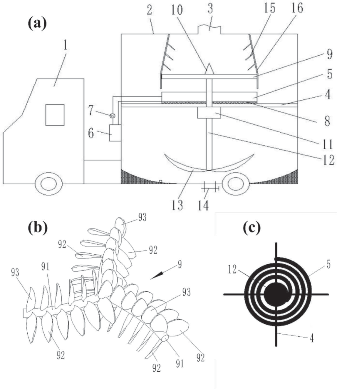
A heating plate (Fig. 1c)) was installed in the insulation control box above the support frame, melting the ice and snow. This heating plate and a heat source system that heats the plate automatically make up the heating device. The heating plate was composed of heating pipes spirally arranged in a horizontal plane. Besides, the entire heat source system comprises pipelines for thermal medium supply, a pump for driving thermal medium, and a heat source. Additionally, a cone for scattering snow was added to limit snow accumulation in the center of the heating plate, spread the snow, and fully utilize the heat conducted by the heating plate. This device was also equipped with a thermostatic medium box to preheat the thermal medium to a set temperature through flange heaters. It served as the cause for reaching the temperature required fast enough for the current efficiency of snow melting while cooperating with the semiconductor heating tubes.
In order to avoid the occurrence of bottom voids and compress the snow, an ice-snow scraping device (Fig. 1b)) with scraper blades was designed to improve melting efficiency. This ice-snow scraping device includes three ice-snow scraping frames and plenty of scraper blades fixed to the ice-snow scraping frame in groups. It was installed above the heating plate and allows for some snow accumulation via a space between the bottom and upper surfaces of the heating plate. The rotation center of the ice-snow scraping device was coaxial with the spiral center of the heating pipes, and it can rotate in the same direction as the spiral direction of the heating pipe. To better compress the blocks of snow and ice together without making them clogged, the scraper blades are parallel to one another and were manufactured at a certain tilt angle (approximately 30°~60°) with the upper plane of the heating plate when placed on the same rod of the scraper frame. The ice-snow breaking blades can break hard snow, ice, and other debris-like branches.
During the work process of this mobile ice-snow melting device, an ice-snow guide groove was designed to divert the snow transported into the device. It is a hollow frustum of a cone connected to the ice-snow inlet. This is a meticulous design with the ability to make all snow and ice fall on the upper surface of the heating plate without spilling and falling into the part of the insulation control box located below the support frame. This approach can also guarantee that the weight of snow and ice measured by weighing sensors mounted on the heating plate is complete. Meanwhile, a certain tilt angle of the ice-snow guide groove and plates for scattering snow on its inner wall can effectively prevent blockage caused by snow adhesion and the rolling of snow masses.
Besides, a rotatable stirring paddle was designed to prevent the snow-melted water from freezing at the bottom of the insulation control box. A rotating shaft connects it to the bearing seat that is installed on the lower portion of the support frame. Furthermore, a spraying mechanism that can automatically spray snow-melting agents was fitted. It activates when a fiber optic sensor for liquid level, positioned at a particular height in the box, determines that there is excessive snow inside the box to be treated. The high sensitivity of these level sensors allows the spraying mechanism to work when it is required without accidentally triggering the actuator when snow falls into the box. In addition, the bottom of the insulation control box is equipped with a mud valve for discharging snow-melted water, stones, branches, and other debris.
Design of the Fuzzy Control-based Intelligent Energy-Efficient Ice-snow Melting System
In order to strengthen the performance of this mobile ice-snow melting device, make it more universally applicable, and work autonomously, a fuzzy control-based intelligent energy-efficient system was founded on the principles of optimal energy use efficiency and a sufficient capacity for melting snow. This system comprises a fuzzy control-based intelligent control system and a hybrid power supply system.
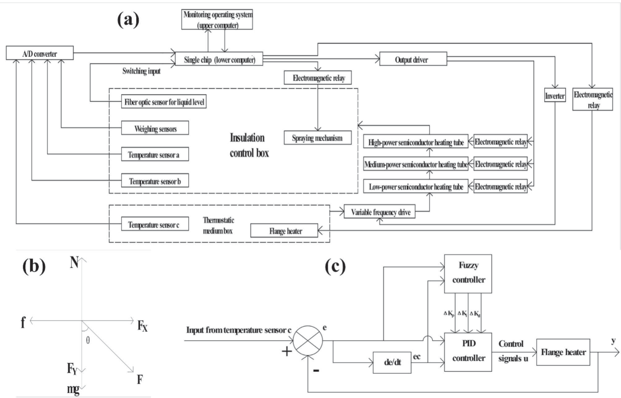
The control system (Fig. 2a)) consists of the monitoring operating system (upper computer), the single chip (lower computer), data acquisition modules like weighing, temperature, and fiber optic sensors, and actuators including semiconductor heating tubes, the flange heater, and the spraying mechanism. According to the automatic control of this system, the supply of the thermal medium could be intelligently regulated based on the weight of snow on the heating plate for energy saving. As the “brain” of this fuzzy control-based intelligent energy-efficient system, the logical design of fuzzy control algorithms integrated into the lower computer plays a crucial role [17]. The input and output variables of the fuzzy controller were set hierarchically in the upper computer. In addition, an interval type 2 single-input fuzzy-PID controller (Fig. 2c)) was devised to boost the stability of the thermal medium temperature that the preheating box can supply, which can respond timely and handle nonlinear, hysteresis, and other issues effectively. Under this control system’s regulation, the theoretical energy-saving potential of this device was evaluated through Monte Carlo stochastic simulation. The full-load power is 9.35 kW. The snow melting rate is 0.432 kg/s (experiment); the snowfall rate is 0.346 kg/s (data source: NOAA). Snow-melted operation weight was divided into (0-20 kg), (20-60 kg), and (60-100 kg), while the corresponding power coefficients are 0.3, 0.7, and 1.0, respectively. The simulation spanning 106 iterations yielded internal frequencies (6.25%, 62.3%, and 31.45%). Under these conditions, the device exhibited an average power of 7.18 kW. Therefore, this control system can theoretically achieve an energy-saving rate of 23.2%.
Fig. 2.
a) The structure of the fuzzy control-based intelligent control system. b) The force analysis of the snow under the ice-snow scraping device. c) The structure of the interval type 2 single-input fuzzy-PID controller.
Due to extremely cold application scenarios, the hybrid power supply system adopts a diesel-electric hybrid architecture. Actuators such as flange heaters, high-temperature-resistant pumps, ice-snow scraping devices, and other supporting modules are electrically powered, ensuring zero-emission operation in these terminal actuation modules. Besides, considering the capacity fade and high cost of battery packs under low-temperature conditions, an on-board generator was deployed to convert chemical energy into electrical energy. This decoupled design separates power generation from actuators, allowing generator replacement with clean energy alternatives (e.g., fuel cells) and direct cable connection to available renewable grids.
Thermodynamic Simulation of the Mobile Ice-snow Melting Device
In order to validate the performance of this mobile ice-snow melting device, the Solidworks® flow simulation module was used for conducting a heat-dissipating simulation of the heating plate without load, which can prove the availability and stability of the physical structure of the design for this device [18].
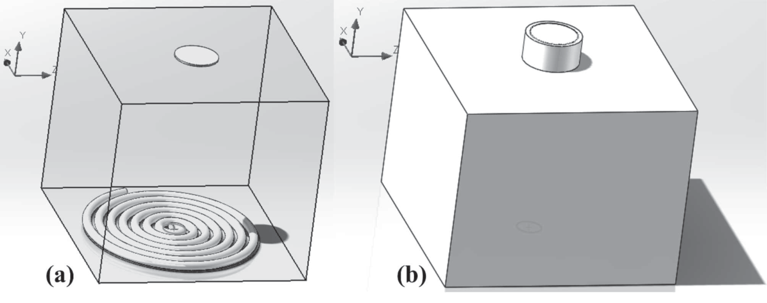
To improve simulation efficiency, accelerate iteration speed, and reduce the impact of unrelated components on the simulation, the physical model had to be simplified by SOLIDWORKS software at first. In order to better reflect the thermal diffusion inside the insulation box, the cover of the heating plate was removed, and its model was simplified to a helical thermal medium pipe (Fig. 3a)). Furthermore, the scraping device and the mechanical parts above it were taken out. Importantly, to improve the reliability of the simulation, a slight rotation was set at the bottom of the fluid field inside the box, which considered the effect of the scraper device during the simulation. Apart from this, the physical model of the insulation control box below the heating plate and its mechanisms were removed (Fig. 3b)), as the primary objective of this work was to simulate the heat supply capacity of the heating plate to the ice and snow above it. However, the upper ice-snow inlet was kept to bring the fluid flow inside the box closer to what occurs during thermal diffusion. Even though the aforementioned simplification of the device can expedite calculation and enhance the quality of mesh division, it was still crucial to assume the following basic conditions while calculating the simulation:
a. The walls of the insulation control box are completely insulated, thus preventing any heat exchange between the inside fluid and the box or its exterior.
Fig. 3.
a) Thermal medium pipe in the computational domain. b) Sketch of the simplified physical model.
b. The heat radiation was ignored during the calculation of the model.
c. The intelligent system’s adjustment to the temperature of the thermal medium was not considered during the simulation process, which means that the temperature of the thermal medium in the helical pipe can remain constant.
d. Snow entering the ice-snow inlet had little impact on the fluid field inside the box.
Then, regarding the configuration of the thermodynamic simulation for the heating plate, the heating plate was set as a stable heat source with a constant temperature of 170ºC. This is because the temperature difference between the inlet and outlet of the thermal medium supply pipes cannot play a role in examining the rationality of the device structure, as there isn’t any snow melting on the heating plate throughout the simulation. The main material of the insulation control box is aluminum oxide ceramic, which has strong insulating power. Besides, the physical characteristics of the simulation medium were set to fluid flow rate and conductivity between different mediums. In terms of processing the model during simulation, cavities that did not meet internal conditions were excluded. In the computational domain, fluids other than physical models and thermal mediums were set to 10ºC air with standard atmospheric pressure. Additionally, the flow type of the fluid was set to laminar and turbulent flow. The ice-snow inlet and the thermal medium pipe were the only fluid outflow and heat source for defining boundary conditions. Grid division was configured as an automatic dividing mode for the fifth level.
Furthermore, the simulation analysis object consisted of global, volume, and surface goals. To ensure the thermal medium was supplied throughout the simulation in a constant temperature form, the maximum and minimum temperature values of the thermal medium pipe were monitored as volume goals. Besides, a series of global goals were monitored, including the total energy balance of the fluid, the average static pressure, the average value of heat flux and wall temperature, and the average, maximum, and minimum values of fluid temperature. When it comes to the configuration of surface goals, an essential part of the calculation results was the fluid temperature on the surface of the ice-snow inlet, including its average, maximum, and minimum values. It was to measure whether the internal heat supply can meet the melted snow demand, evaluate the efficiency of heat transfer within the box, and provide theoretical support for optimizing the intelligent energy-efficient system for regulating the temperature of the thermal medium.
Experimental Study on the Ice-snow Melting Performance of the Device
It is also essential to conduct a laboratory test to explore the snow-melting performance of the device under various working conditions and the effects of key actuators. Key actuators include the heating plate, the scraper blades, and the high-temperature-resistant pump for supplying thermal medium. The temperature of the heating plate determines the temperature difference, which is directly proportional to the heat exchange rate; the rotary speed of the scraper blades determines the specific surface area of snow blocks or the effective area of them to be heated; and the flow rate of the high-temperature-resistant pump determines the heat supply capacity of the heating plate. Therefore, the data from this test could also be regarded as guidance for further design of the working parameters of the intellectualized thermal energy utilization system to adapt to the actual application of this device on roads.
In terms of the working parameters of the device in the experiment, these key actuators are three important variables. Table 1 shows a comprehensive experimental plan with 3 factors at 3 levels was designed. With a gradient of 70ºC, the operating temperatures of the heating plate were set at 100ºC, 170ºC, and 240ºC, which were marked as A1, A2, and A3, respectively. The flow rates of the high-temperature-resistant pump were set at 1.2 m³/h, 1.35 m³/h, and 1.5 m³/h, which were marked as B1, B2, and B3, respectively. The rotary speeds of the scraper blades were set at 0 r/min, 700 r/min, and 1400 r/min, which were marked as C1, C2, and C3, respectively. After this, melting snow experiments with different qualities under operating conditions were conducted for cost accounting.
Table 1.
The comprehensive experimental plan with 3 factors at 3 levels.
| C1 | C2 | C3 | ||
|---|---|---|---|---|
| A1 | B1 | A1B1C1 | A1B1C2 | A1B1C3 |
| B2 | A1B2C1 | A1B2C2 | A1B2C3 | |
| B3 | A1B3C1 | A1B3C2 | A1B3C3 | |
| A2 | B1 | A2B1C1 | A2B1C2 | A2B1C3 |
| B2 | A2B2C1 | A2B2C2 | A2B2C3 | |
| B3 | A2B3C1 | A2B3C2 | A2B3C3 | |
| A3 | B1 | A3B1C1 | A3B1C2 | A3B1C3 |
| B2 | A3B2C1 | A3B2C2 | A3B2C3 | |
| B3 | A3B3C1 | A3B3C2 | A3B3C3 | |
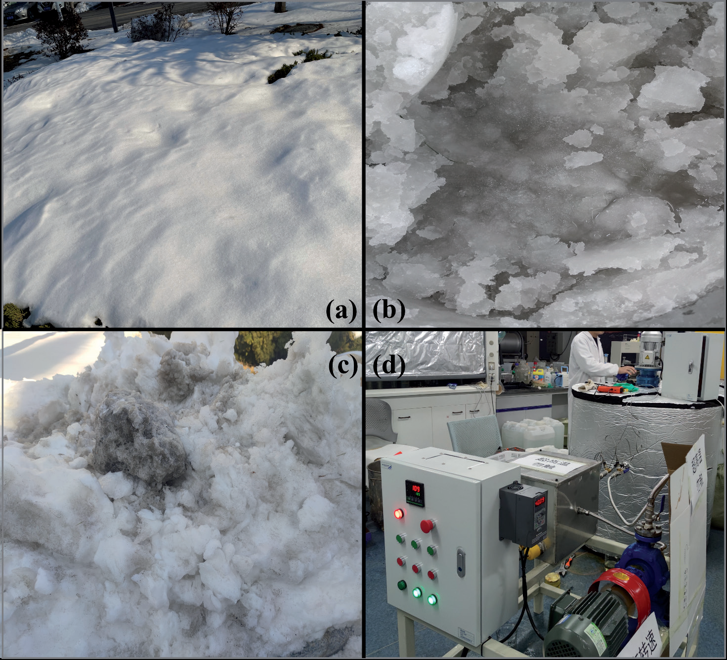
According to the actual application scenarios of this device, 3 different kinds of snow were considered as samples: powdery snow, slushy snow, and icy snow [19]. Powdery snow (Fig. 4a)) refers to fresh snow that is mostly untouched by pedestrians and vehicles. After heavy snowfall, under the effects of sunlight, vehicle crushing, and pedestrian trampling, the snow gradually begins to melt, generating sticky snow with a small amount of water mixed in, which was regarded as slushy snow (Fig. 4b)) in this study. Icy snow (Fig. 4c)) typically develops in areas where snow accumulates from clearing or where cleanup is neglected for a long time after heavy snow. It appears in a block shape with a high density and naturally melts extremely slowly due to the snow crust generated after repeated melting and freezing [20]. In order to mitigate the effect of different snow compositions on snow-melting efficiency, snow samples were collected from the same site (urban roads or street sides at No. 17 Chunhui Road, Yantai, China) in the same period. During the process of experiments, the monitoring values include the melting time of snow on the heating plate, the real-time temperature of the thermal medium at the inlet and outlet of the heating plate in the insulation box during the entire process of snow melting, and the temperature of the air that is close to the heating plate inside the insulation control box. A total of 81 experiments around 3 types of snow under 27 different operating modes of this device were conducted in the laboratory (Fig. 4d)). The sample mass of snow input each time is 2 kg. By comparing the snow-melting efficiency in the above experiments, this study could better demonstrate the device’s performance in various snow-clearing scenarios and explore the optimum working parameters controlled by the intellectualized thermal energy utilization system.
Results and Discussion
Results and Discussions of the Thermodynamic Simulation of the Mobile Ice-snow Melting Device
Following 88 iterations of the fluent solver, the calculation results converged. As the volume goals were monitored, the maximum (Fig. 5a)) and minimum (Fig. 5b)) values of the temperature of the thermal medium pipe surface were at 170ºC all the time. The contour map of the surface temperature of the heat pipe (Fig. 5c)) indicates that the temperature of the thermal medium pipe stays constant at 170ºC throughout the simulation, as assumed. Since the temperature stability of the sole heat source in this simulation, the availability of simulation data can be proved, and the influencing factors are easier to lock [21].
In order to better analyze the temperature distribution of the fluid inside the insulation control box, a comprehensive line chart (Fig. 6a)) was generated, including the average temperature of fluids within the domain, the average value of fluid temperature on the surface of the ice-snow inlet, and the average value of wall temperature. The temperature turning points and warming tendencies on their temperature curves are almost identical. The average value of wall temperature shows high-temperature response speed, while the fluid temperature hysteresis on the surface of the ice-snow inlet is rather noticeable due to the long distance between the inlet and the heat source. Thus, snow that falls on the wall can be melted by the heat that remains after the wall has been heated, minimizing the heat loss and energy waste. When the average temperature of fluids within the domain reaches approximately 100ºC, the fluid temperature on the surface of the ice-snow inlet begins to rise rapidly. This is because the heat flux in the fluid domain has reached its peak, and the heating capacity is currently sufficient [22]. Combined with the comprehensive line chart (Fig. 6a)), the global temperature curve chart (Fig. 6b)), and the contour section view chart (Fig. 5d)), it is to conclude that fluid temperature rise in the computational domain is highly uniform and steady. In this way, the rationality of the internal layout of the device and the reliability of the heat supply method are demonstrated [23]. Besides, according to the fluid temperature on the surface of the ice-snow inlet (Fig. 6c)), the conclusion is that the surface temperature here varies dramatically when the heat flux is insufficient. Combined with the simulation results, it could be considered to install a temperature sensor near the surface of the snow inlet and create a control algorithm to make the intelligent energy-efficient system more sensitive to optimize the device’s functionality. For example, when the feedback value from the temperature sensors exceeds 100ºC and there is less variation, the intelligent energy-efficient system could reduce the heat supply; when the temperature feedback from the temperature sensor approaches a stable value, the control system may significantly reduce the supply of heat, because it indicates excessive heat inside the insulation control box. When the temperature feedback from the temperature sensor remains low for a long time and fluctuates greatly, increasing the heat supply or activating the spraying mechanism to accelerate the process of snow melting can be considered by the control system because it is possible that this device’s snow-melting capacity may be currently insufficient at that time.
Fig. 5.
a) The maximum value of the temperature of the thermal medium pipe. b) The minimum value of the temperature of the thermal medium pipe. c) The contour map of the surface temperature of the heat pipe. d) The contour section view chart.

Fig. 6.
a) The comprehensive line chart. b) The global temperature curve chart. c) The fluid temperature at the surface of the ice-snow inlet.
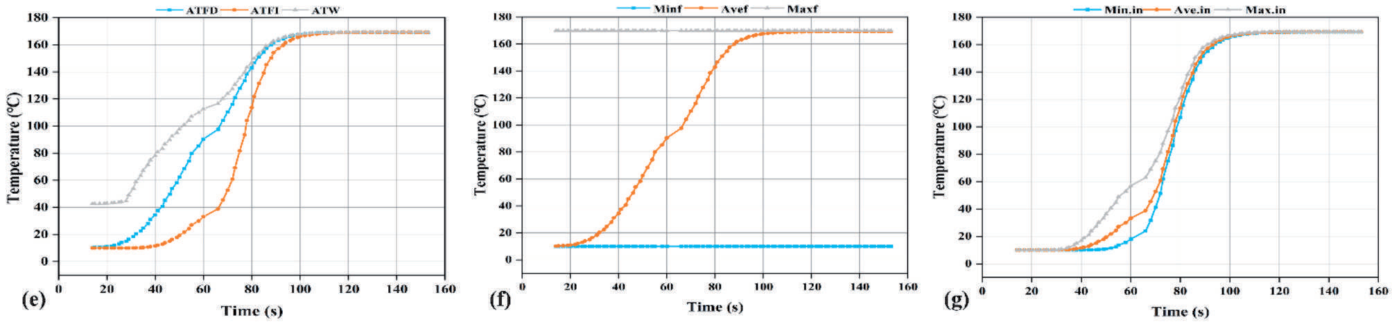
Fig. 7.
a) The global static pressure in the fluid domain. b) Flow trajectory of the fluid field. c) The contour vector profile. d) The global heat flux chart. e) Sketch of the heat flux of heating pipes. f) Total energy balance chart.
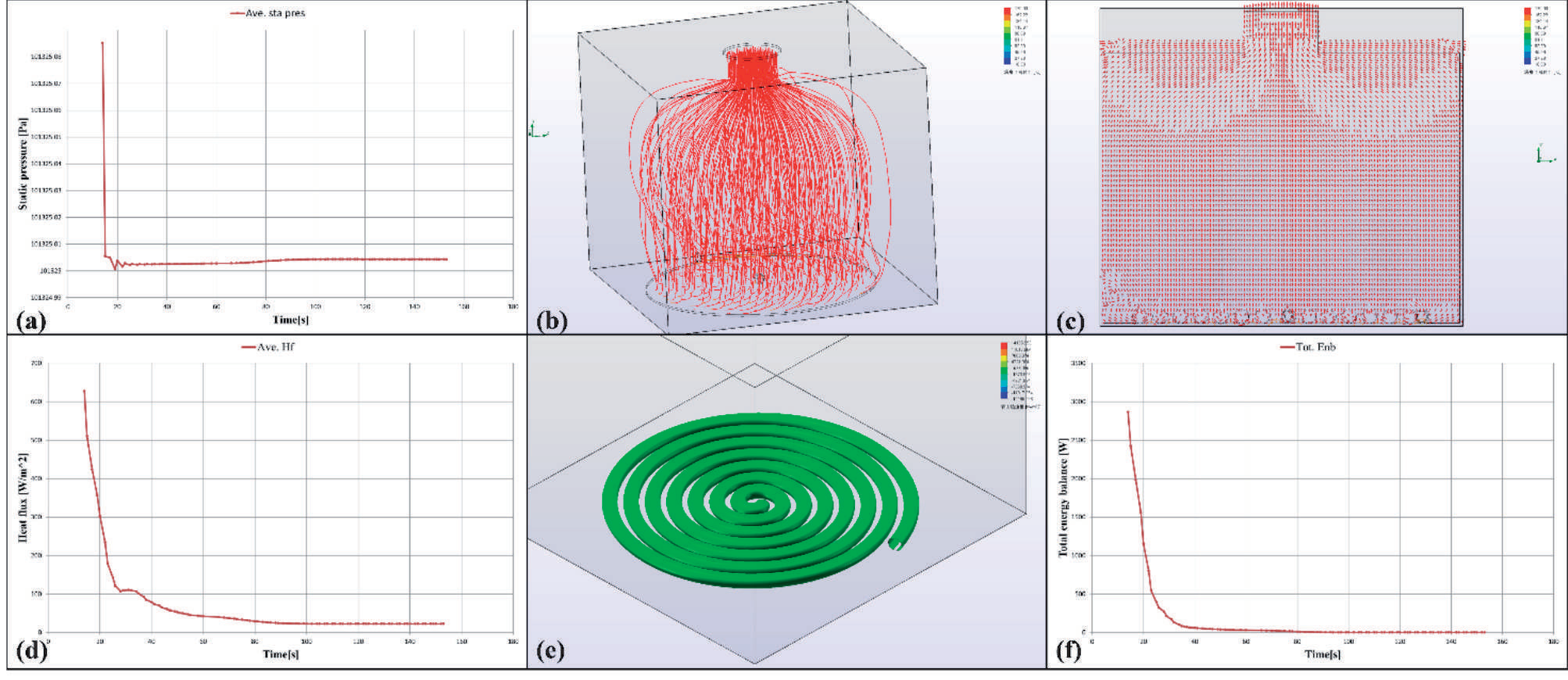
Additionally, by monitoring the global static pressure in the fluid domain (Fig. 7a)), it can be concluded that the global pressure tends to stabilize in a short period of time once the heat source starts working. This means that the structural layout of the device is appropriate with little disturbance to heat conduction. Furthermore, there is virtually little variation in the fluid domain’s pressure when the insulation box’s interior reaches a high temperature. Thus, the reliability and stability of the chosen heat supply technique could be proved.
The thermal medium within the heating plate will conduct heat to the snow when it is covered, while the air above will be heated if there is no snow on the heating plate. As shown in Fig. 7b), the heated air may rotate due to the operation of the scraper, exhibiting a spiral upward trend overall. In this way, the snow on the heating plate will melt more quickly because there will be more surface area in contact with the heated air.
In the contour vector profile (Fig. 7c)), the distribution of vector contour could reflect the distribution of heated air, and its density can reflect the heat density of a specific area [24]. The heated air tends to move outward from the ice-snow inlet due to the expansion of the gas inside the insulation control box. Therefore, a “bowl-shaped” low-pressure zone forms near the ice-snow inlet due to its tiny size. A pressure difference from the circumference of the barrel to the center is generated as the edge of the low-pressure zone inside the box is tangent to the ice-snow inlet. In this way, a force from the barrel could be applied to the newly delivered snow in the direction of the center, which facilitates the collection of snow and makes it fall onto the snow plate. Additionally, the spiral-distributed structure of the bottom thermal medium pipe creates a vortex fluid field near the box wall. This could not only prevent the occurrence of snow voids on the heating plate but also promote full contact between snow and the heat source to create a thermal field with the heat-enveloping effect. Therefore, the heated air can envelop snow particles as soon as possible, allowing them to fully absorb the internal heat coupled with the stirring of the scraper blades. Combined with the simulation results, the area of the heating plate ought to account for about two-thirds of the bottom area of the insulation box. Therefore, the phenomenon of snow being hard to keep in touch with the edge of the heating plate can be avoided to fully utilize the heat of the thermal medium.
Fig. 7d) and Fig. 7e) show the heat flux of the computational domain and thermal medium pipe, respectively. The heat flux can react to temperature differences [25]. Thus, the heat inside the box stops flowing and reaches a state of thermal equilibrium as it approaches the equilibrium temperature (Fig. 7f)). As this figure illustrates, the fluid domain quickly reaches a steady state, and the heat field quickly reaches a condition of thermal equilibrium once the heating plate is operating. Meanwhile, the heat flux on the surface of the thermal medium pipe is roughly three times that of the surrounding fluid, confirming the adequate heating capacity of this device and the necessity of intelligent energy-efficient systems for improving energy utilization efficiency.
Results of the Experiment and Discussions on the Performance of the Device
The melting time of snow on the heating plate and the temperature of the air that is close to the heating plate inside the insulation control box were recorded in detail (Supplementary Table S1). The real-time temperatures of the thermal medium at the inlet and outlet of the heating plate in the insulation box during the entire process of snow melting were also recorded by a high-accuracy thermometer with four channels. Changes in temperature difference can be used to determine the heat supply capacity of the device.
As Table 2 shows, a three-factor analysis of variance was conducted with SPSS® software to study the relationship between the three variables and the melting time of snow based on the results above. It can be concluded that the effect of the set temperature of the thermal medium on the melting time of snow is significant (F = 44.747, p = 0.000<0.05, partial η² = 0.591>0.14, 95% CI [0.47, 0.69]). Fig. 8a) shows the mean melting time of snow at different set temperatures of the thermal medium. It can be observed that the melting time of snow significantly decreases with the increasing set temperature of the thermal medium. Furthermore, this stimulating effect becomes less strong as the set temperature of the thermal medium rises. Consequently, the set temperature of the thermal medium doesn’t need to be extremely high in light of energy conservation.
Additionally, the effect of the flow rate of the high-temperature-resistant pump on the melting time of snow is significant (F = 4.385, p = 0.017<0.05, partial η² = 0.124, 95% CI [0.008, 0.23]). Fig. 8b) shows the mean melting time of snow at different flow rates of the high-temperature-resistant pump. It can be found that the effectiveness of snow melting can be increased by increasing the flow rate of the high-temperature-resistant pump, but this impact is not noticeable at high flow rates. Importantly, the effect of the rotary speed of the scraper blades on the melting time of snow is the most significant (F = 95.327, p = 0.000<0.05, partial η² = 0.755>0.14, 95% CI [0.66, 0.82]). Fig. 8c) shows the mean melting time of snow at different rotary speeds of the scraper blades. Compared to not rotating the scraper blades, the work of this part results in a several-fold increase in snow-melting efficiency. Therefore, the design of the scraper blades proved to be efficient. However, it still suffers from a decrease in the significance of the effect in the high-speed range.
Table 2.
The results of three-factor analysis of variance.
Fig. 8.
a) The mean melting time of snow at different set temperatures of the thermal medium. b) The mean melting time of snow at different flow rates of the high-temperature-resistant pump. c) The mean melting time of snow at different rotary speeds of the scraper blades. d) The mean melting time of snow under the second-order interaction effects between the rotary speed of the scraper blades and the set temperature of the thermal medium.
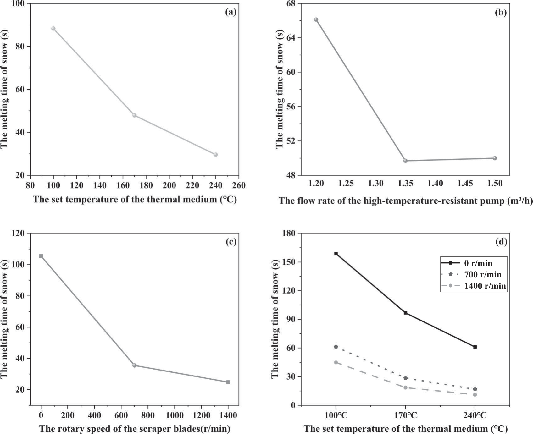
The ranking of the effect on the snow’s melting time is the rotary speed of the scraper blades > the set temperature of the thermal medium > the flow rate of the high-temperature-resistant pump. Therefore, appropriately increasing the scraper blades’ rotary speed and decreasing two other working parameters can be considered under the same snow-melting efficiency. This is because driving the rotary of the scraper blades is more energy-saving than heating the thermal medium to a high temperature. These indicate that the device has sufficient working margin and stable snow-melting performance.
Given the significant effect of the rotary speed of the scraper blades and the set temperature of the thermal medium, it is meaningful to further study the second-order interaction effects between them and another variable. Table 2 shows that both the set temperature of the thermal medium × the flow rate of the high-temperature-resistant pump (F = 1.099, p = 0.365>0.05, partial η² = 0.066, 95% CI [0.001, 0.11]) and the flow rate of the high-temperature-resistant pump × the rotary speed of the scraper blades (F = 0.229, p = 0.921>0.05, partial η² = 0.015, 95% CI [0.001, 0.06]) do not appear to have a significant effect, which means there is no second-order interaction effect between them. However, the combined impact of the thermal medium’s set temperature and the scraper blades’ rotary speed is significant (F = 4.873, p = 0.002<0.05, partial η² = 0.239>0.14, 95% CI [0.018, 0.34]). Therefore, Fig. 8d) revealed that a steady tendency to flatten and a minor standard deviation occur when the efficiency of this device in melting snow reaches a particular level. Table 3 compares the absolute effects per unit temperature change. It revealed that increasing the thermal medium temperature by 10°C reduced melting time by 7.0s on average (from 158.74 s to 61.01 s) at 0 r/min but only by 2.4 s (from 44.87 s to 11.11 s) at 1400 r/min. This indicates that high scraper speed substantially attenuates the temperature effect, aligning with the significant interaction (η² = 0.239 compared to temperature’s η² = 0.591).
Table 3.
The melting time of snow at different rotary speeds of the scraper blades or set temperature of the thermal medium (mean value±standard deviation).
| 0 r/min (n = 27) | 1400 r/min (n = 27) | 700 r/min (n = 27) | |
|---|---|---|---|
| 100ºC | 158.74±47.34 | 44.87±23.36 | 61.26±31.62 |
| 170ºC | 96.72±22.24 | 18.48±4.61 | 28.46±14.31 |
| 240ºC | 61.01±23.22 | 11.11±5.59 | 16.73±9.76 |
The ambient temperature in the laboratory was approximately 5ºC. The insulation control box was wrapped in aluminum silicate material, which is resistant to high temperatures and provides a strong insulation effect. Fig. 9a) shows that the temperature inside the insulation control box can increase relatively steadily with the increase of the set temperature of the thermal medium, providing sufficient ambient temperature for snow melting. However, the ice-snow inlet has to be regularly opened and closed to confirm the melting of the snow, resulting in excessive temperature loss and a lower temperature at the outlet of the heating plate after the snow melts. The temperature difference between the inlet and outlet of the heating plate after snow melts can be calculated by the temperature difference before and after snow melts. Therefore, future working parameter designs for the device can be made more efficient in terms of thermal utilization by researching the effects of various working factors at various levels on the temperature differences before and after snow melts.
Based on the mean change in temperature difference at different set temperatures of the thermal medium (Fig. 9b)), it can be found that the higher the temperature of the heating plate, the greater the heat loss and the relatively lower the heat utilization rate. This results from excessive expansion of the air inside the insulation box at high temperatures and the requirement to verify whether the snow has melted. Fig. 9c) shows that the high flow rate of the pump can ensure sufficient heat supply capacity to partially compensate for the loss of heat inside the box. However, this is insufficient compared to the substantial heat loss brought on by the quick airflow at the open snow inlet. Additionally, the mean changes in temperature difference after the snow melts were considerably increased by the work of the scraper blades (Fig. 9d)). This is because the high-speed rotation of the scraper blades accelerates the flow and escape of heated air. At the extremely high speed of the scraper blades, the change in temperature difference decreased slightly. This is mostly because snow melts quickly at high speeds, indicating the device’s effective snow-melting capabilities.
Fig. 9.
a) The mean temperature of the air in the insulation control box at different set temperatures of the thermal medium. b) The mean change in temperature difference between the inlet and outlet of the heating plate after snow melts at different set temperatures of the thermal medium. c) The mean change in temperature difference between the inlet and outlet of the heating plate after snow melts at different flow rates of the high-temperature-resistant pump. d) The mean change in temperature difference between the inlet and outlet of the heating plate after the snow melts at the different rotary speeds of the scraper blades.
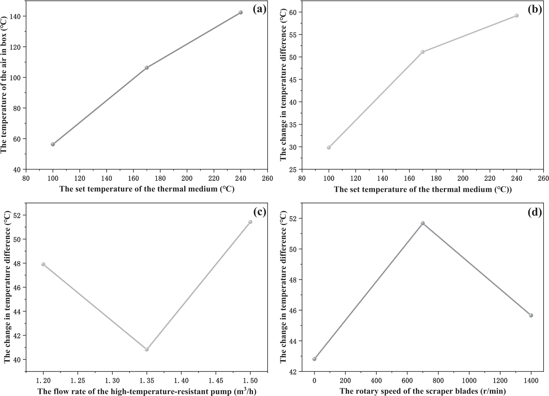
Fig. 10.
The melting time of the powdery snow, slushy snow, and icy snow under different operating modes.
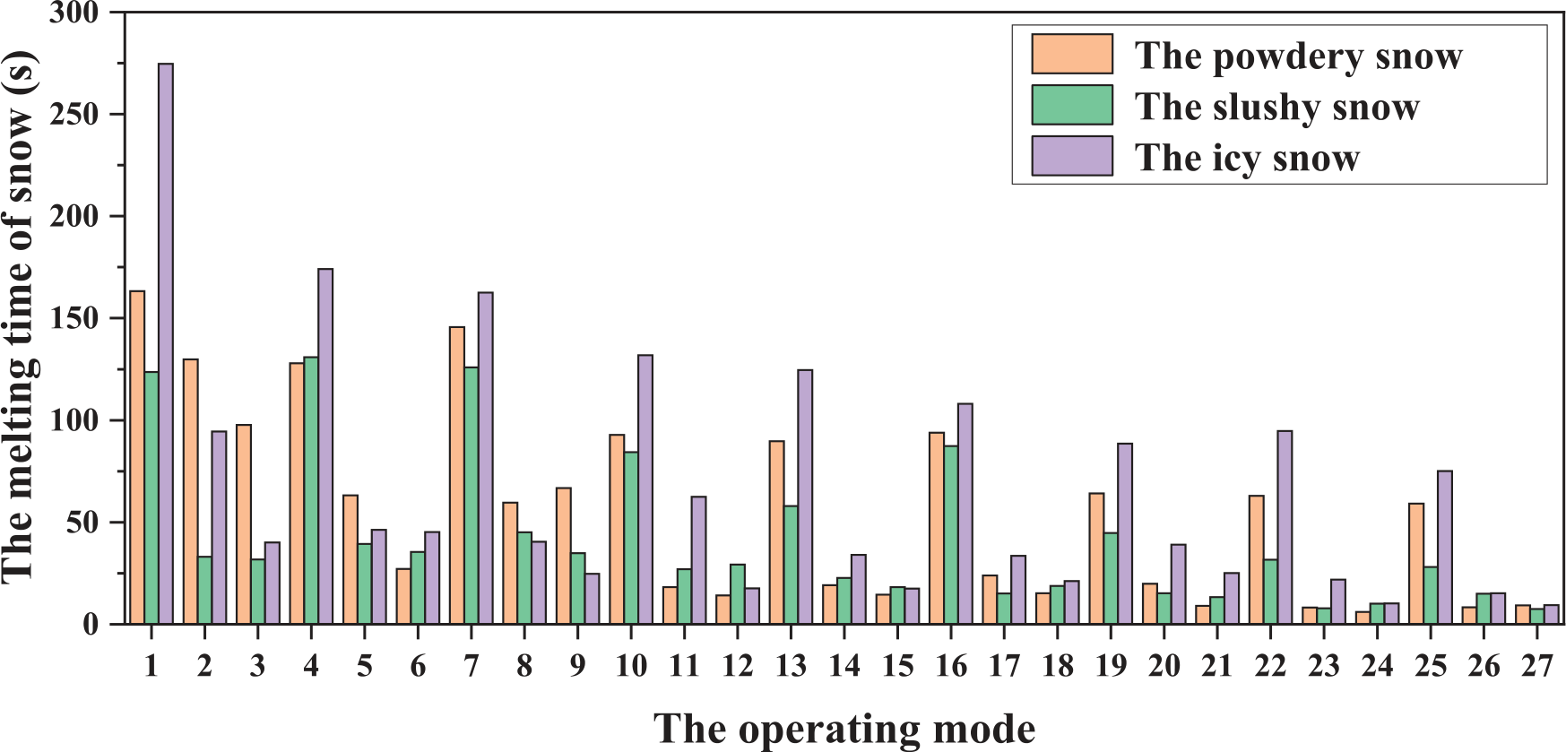
Finally, every operating mode was used as an independent variable to analyze the melting time of the powdery snow, slushy snow, and icy snow (Fig. 10). Each operating mode has a number that corresponds to the sequence of experiments in the Supplementary Table S1. In most operating modes, the melting efficiency of this device is approximate for these three types of snow. For icy snow, the work of the scraper blades has a relatively significant impact on the melting time of snow. Therefore, the design of this device can adapt to most snow-melting work on the spot in practical application scenarios on urban roads. For example, it can play an important role on urban roads that are covered by fresh snow, snow crushed by vehicles, long-term accumulated snow, etc.
Material Flow Cost Accounting (MFCA) for the Mobile Ice-snow Melting Device and Policy Implications
The energy flow during snow melting was summarized first as an essential part of material flow management. Then, a cost accounting and life cycle carbon emission analysis for this mobile ice-snow melting device were conducted.
An energy flow model for heat exchange was established to trace energy flows based on the relationship between heat provision and heat demand. The amount of heat required for melting snow on a heating plate QX is:
where C0 is the specific heat capacity of ice, m1 is the total mass of snow entering per unit time, T0 is the initial temperature of snow at the ice-snow inlet, L is the heat of ice dissolution, C1 is the specific heat capacity of water, and T1 is the average temperature of the snow-melted water.
m1 was measured in real-time by several weighing sensors with a multi-point layout (approximately 10~50). In this way, this design can still minimize the difference between the actual gravity of snow accumulated and the measurement value of weighing sensors, even if snow distribution on the heating plate is uneven. The values measured by weighing sensors must be converted because of the pressure from the ice-snow scraping device. Given the force analysis (Fig. 2b)), the accurate weight of snow is:
where N is the value of supporting force measured by the weighing sensor, Gp is the gravity of the heating plate and internal thermal medium, μ is the friction coefficient on the surface of the heating plate, θ is the angle between the scraper blade and the plane on the heating plate, g is the gravitational acceleration.
The amount of heat conducted by the heating plate QF is:
where, C2 is the specific heat capacity of the thermal medium, m2 is the mass of the thermal medium, ΔT2 is the temperature difference between the inlet and outlet of the thermal medium supply pipes.
The total mass of the thermal medium is the sum of the mass of the thermal medium in the heating plate and the supply of the thermal medium per unit of time, which is:
where, ρ2 is the density of the thermal medium, S2 is the cross-sectional area of the thermal medium supply pipes, l is the length of pipes preset in the heating plate, and q is the flow rate of the variable-frequency pump.
The value of ΔT2 is:
where T2 and T3 are temperatures of the inlet and outlet of the thermal medium supply pipes, respectively.
However, the insulation control box cannot be completely insulated. In order to simplify the energy flow model for this ice-snow melting device, the following assumptions were established:
a. The physical characteristics of the thermal medium and ice-snow do not change during the heat exchange process.
b. Currently, the insulation control box is regarded as a separate entity, and its heat exchange with the external environment is not considered.
c. Convective heat transfer served as the foundation for the snow-melting process. The heating plate did not decrease the thermal medium’s heat transfer efficiency.
Given Fourier’s law of heat conduction, the relational equation between the heat required for melting snow and the heat conducted by the heating plate is:
Due to the heat dissipation during the work of the heating device, K, a modifying factor was considered while modeling. The modified relational equation is:
Therefore, the heat exchange equation of this energy flow model is:
Additionally, this model for the intelligent energy-efficient system could also calculate and solve the instant heat demand for snow melting and the heat supply capacity of the thermal medium to attain the expected efficiency in melting snow.
In terms of the cost accounting for this mobile ice-snow melting device, the total expenditure (TOTEX) of mechanical snow removal vehicles and snow-melting agent spreading vehicles was also considered. They were compared to assess the financial feasibility of the mobile ice-snow melting device.
Table 4 shows the cost accounting for these snow removal methods (unit: CNY). Capital expenditure (CAPEX) is composed of costs on loadable vehicles, snow collection devices, and integrated devices. Operating expenditure (OPEX) of them consists of fuel cost, energy cost, material cost, and extra transportation cost. Due to the requirement of quantifying the amount of snow in the calculation of OPEX, taking removing snow within 10 km of the road as an example. During the period of experimental study, the average snowfall in Yantai City was 10.4 mm (data source: Shandong Meteorological Bureau, 2023). Assuming the snow cover on the road has a consistent thickness, the single-lane road width is 3.5 m. The parameterized snow density is 0.18 g/cm3 [26]. The amount of this snow is:
Based on the fuel consumption of the vehicle and local oil prices, the fuel costs of the heavy dump truck and medium truck are ¥3.9/km and ¥1.17/km, respectively. Besides, the electricity cost of diesel generators is ¥1.81/kWh. The power of the agent spreading device is 12 kW, while the total power of the mobile ice-snow melting device is 9.35 kW. Assuming the working speed of the snow-melting agent spreading vehicle is 20 km/h. Thus, its energy cost (electricity) per 10 km is ¥10.86. Additionally, the surface area for heat conduction between the heating plate and the insulation box of this laboratory device remains constant. Combined with Fourier’s law and the energy flow model established in this paper, it can be concluded that the melting efficiency of this device can be stabilized in a range. For experiments d1-d8 (Supplementary Table S1), the snow melting efficiency is 23.15 s/10 kg. Thus, the energy cost of the mobile ice-snow melting device is ¥713.04. In terms of material cost, a low-cost solid snow-melting agent can efficiently melt snow when its mass ratio to snow is 1:10 [27]. The price of it is ¥724/t. Thus, the material cost of it is ¥4743.648. Additionally, there is an extra transportation cost for mechanical snow removal vehicles to move snow away from crowded areas of cities. Assuming that the snow has melted to one-third of its initial amount by the time it is required to be transported and the average distance to suburbs is 10 km. Given the rated load capacity of the heavy dump truck is 15 t and the dump truck is empty when it returns from transporting, its extra transportation cost is ¥195.
Table 4.
The cost accounting for three different snow removal methods (taking removing approximately 65.52 t of snow within 10 km of the road as an example).
Although the work of mechanical snow removal vehicles doesn’t require any other devices besides the collection device, the initial CAPEX for them is still much higher than others. Besides, this method requires more vehicles to work simultaneously on multiple lanes, significantly increasing the initial investment. Compared with melting snow on the spot, transporting accumulated snow out of the urban area is also a significant operational burden for the government, which may also cause unnecessary energy waste. Therefore, municipal policies can focus more on cost-efficient snow-melting vehicles in cold cities to alleviate urban energy poverty. Additionally, although the CAPEX of snow-melting agent spreading vehicles is comparable to that of the mobile ice-snow melting device, the former consumes vast quantities of solid agents while applying, especially in some cities troubled by frequent snowfall. This means higher operating costs for keeping roads cleared with this method. Furthermore, the negative impact of snow-melting agents on the environment, ecology, and infrastructure cannot be underestimated, resulting in the ban policy on snow-melting agents in some cities. For some underdeveloped cities or regions, the 10-year operational life cycle cost analysis (Supplementary Table S2) reveals that the annual capital assets expenditure can be reduced to ¥8925.637 via financial instruments such as loans (Supplementary Table S3 for loan details). The initial investment barriers can also be mitigated via cross-regional vehicle sharing between neighboring cities. Based on the lower OPEX and long service life, the marginal TOTEX of this melting device can be dramatically lowered annually compared to the other two constant marginal costs.
Furthermore, the life cycle carbon emission analysis (Supplementary Table S4, S6) helps to better assess the environmental impact of this ice-snow melting system based on collected data (Supplementary Table S5). By eliminating the need to transport large quantities of snow, this system can reduce 6114.62 t CO₂ emissions over its entire lifecycle (reducing 79.59% of the emissions of the traditional method). The majority of this reduction (approximately 6091.84 t) can be achieved through the design of snow melting on the spot during its frequent operations over a 10-year lifespan. This emission reduction may yield roughly ¥483814 ( data source: Shanghai Environment and Energy Exchange) in carbon credit trading income, progressively lowering annual fixed capital expenditure year by year. Although this system emits 1.51 t more CO₂ per use compared to snow-melting agent spreading vehicles, it has a significantly lower impact on infrastructure and the environment, including reduced infrastructure corrosion and minimized ecological harm from chemical runoff. Furthermore, with advancements in sustainable energy technology, the system’s carbon footprint can be further reduced in the future. Against the background of increasingly strict environmental policies, there will be more relevant subsidy policies to boost the investment in this mobile ice-snow melting device for wide application based on its potential for upgrading clean energy technology. In conclusion, this mobile ice-snow melting device is not only more energy-saving and environmentally friendly but also highly cost-effective in practical applications compared to others.
Therefore, this work may have profound implications for policymakers in cold regions. Currently, most policies surrounding snow-melting agents are recommendation-only because it is still challenging to replace their function, making it tough to implement regulations. Due to their extremely high costs, some environmentally friendly snow-melting agents only apply on a few roads, such as airport runways. However, more countries and regions will introduce mandatory snow-melting agent ban policies after this device is widely promoted. The government can enforce the policy of a stricter prohibition on snow-melting agents after overcoming the dilemma of snow-melting efficiency. Additionally, it can be possible to develop more comprehensive production standards for environment-friendly snow-melting agents that progressively transform from an economic to an environmental orientation. Therefore, environmental policies could concentrate more on preventing snow removal-related pollution of roads, water, plants, and other fields. For example, in addition to specifying the corrosion rate of carbon steel and heavy metal content, these standards can also limit the levels of COD, phosphorus, sulfur, and other indicators of liquid snow-melting agents. In this way, municipal managers can focus on combining multiple snow removal methods to reduce costs and improve energy efficiency. Upgrading the renewable energy system of the device in the near future can greatly reduce the use of fossil fuels and carbon emissions during snow removal and promote the development of energy transition policies [28].
Conclusions
In this paper, a novel intellectualized thermal energy utilization system that integrated multiple ice-snow melting devices and an intelligent energy-efficient system was designed to melt heavy snow immediately on the spot under various practical application scenarios of urban roads with lower energy consumption. The physical structure of this design proves to be competent for taking full advantage of the thermal field generated internally with the heat-enveloping effect, promoting full contact between snow and the heat in the device without bottom voids. Importantly, key findings reveal that the thermal medium’s set temperature and the scraper blades’s rotary speed can jointly play significant second-order interaction effects, which can be used to optimize working parameters and maximize snow melting efficiency based on energy saving. The energy flow model for heat exchange proposed in this study is the foundation for handling snow on-site in an energy-efficient way instead of delivering it away. This interdisciplinary method, integrated with material flow management, cost accounting, life cycle carbon emission analysis, and technology application, presents sufficient potential for optimizing policy and promoting technology. Future research can focus more on establishing green energy systems for the heat supply of the device, such as making the electricity supply more environment-friendly or utilizing clean energy for direct heating.