

Introduction
Buildings located in poor service environments are susceptible to corrosive media, moisture, high temperatures, heavy loads, and improper maintenance, among other factors. Over time, these conditions can undermine or even disable the durability and functionality of the buildings before their intended design life. Such deterioration directly impacts the normal order of life and work, as well as the safety of individuals and property, leading to significant economic losses and social consequences [1-5].
For buildings with reinforced concrete structures, the deterioration of their durability can be classified into two types: one resulting from the corrosion and degradation of the concrete materials themselves [6-8], and the other from the corrosion of reinforcement bars within the concrete [9-11]. Numerous examples have demonstrated that the latter factor significantly contributes to the deterioration or failure of reinforced concrete.
The corrosion of reinforcement bars inside the concrete is primarily caused by concrete carbonization and the erosion of chloride ions. Carbon dioxide (CO2) in the atmosphere reacts with calcium hydroxide (Ca(OH)2) in the concrete, forming calcium carbonate (CaCO3), which reduces the alkalinity of the concrete. When the pH value reaches or falls below 9, the passivating films on the reinforcement bars become unstable, and the bars, without the protection of these films, start corroding under certain environmental conditions [12-15]. Additionally, even at low concentrations, chloride ions can significantly destroy the passivating films on the reinforcement bars, further promoting corrosion under specific conditions [16].
While carbon dioxide constitutes a small proportion of the natural atmosphere (only about 0.03%), and the carbonization rate of concrete is relatively slow in the natural environment, over a long period (e.g., several decades), reinforcement bars are susceptible to carbonization and subsequent corrosion after the passivating films are destroyed. The natural environment contains various sources of chloride ions, such as oceans, offshore areas, inland salt lakes, and chemical industries that produce corrosive media like hydrochloric acid and chlorine [17-20]. Experimental results indicate that chloride ions diffuse into concrete at a faster rate than the rate of concrete carbonization, making substances with chloride ions significantly contribute to the prevalence and severity of reinforcement bar corrosion in concrete [21].
Furthermore, studies have shown that the combined effects of carbonation and chloride ions are greater than the effects of each factor considered individually [22, 23]. Carbonation has a profound influence on the transport of chloride ions within building structures. Specifically, carbonation significantly increases both the diffusion rate and content of chloride ions, which detrimentally affect the working life of structures [21]. Carbonation can release bound chloride ions, turning them into free ions. The chloride ion content in carbonated concrete is significantly higher than that in non-carbonated concrete, and carbonation even facilitates the migration of chloride ions [24].
Special attention should be given to the poor durability performance of reinforced concrete structures in offshore areas, as highlighted by numerous scholars [25]. For instance, in a power station’s booster station that has been in service for 26 years, 70% of the concrete columns and 25% of the concrete beams exhibit severe durability damages, such as longitudinal cracks and exposed bars. Moreover, concrete members in the tidal range zone of a wharf that directly interacts with seawater suffer extensive corrosion from chloride ions. Investigations indicate that wharves in service for 20 to 30 years generally exhibit serious durability problems.
This paper focuses on a reinforced concrete house in an offshore area that has been in service for 35 years. Through on-site investigations, assessment of the house's condition, analysis of visible damages, and examination of the compressive strength of load-bearing concrete beams and columns, the damage mechanism of concrete materials and internal reinforcement bars is scrutinized using microscopic inspection methods. Finally, with the assistance of relevant structural calculation software, the overall safety and safety grade of the house's current state are calculated and analyzed. Conclusions are drawn, and appropriate recommendations are proposed.
Material and Methods
An Overview of the House and Detection Methods
Location of the House and the Climate
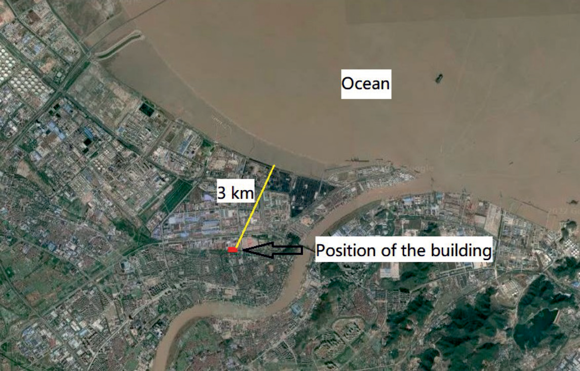
The house is situated approximately 3 kilometers away from the sea, as illustrated in Fig. 1. The region falls within the subtropical monsoon climate zone, known for its mild and humid climate, distinct four seasons, abundant sunshine, and rainfall. The average annual temperature in the area is 16.3ºC, and the annual precipitation ranges from 1310 to 1370 mm. On average, there are 148 rainy days throughout the year. Typhoons commonly occur during the summer and autumn seasons. Spring is characterized by lower temperatures and increased rainfall, while cloudiness and rain are prevalent features of the autumn season.
An Overview of the Architectural Design of the House
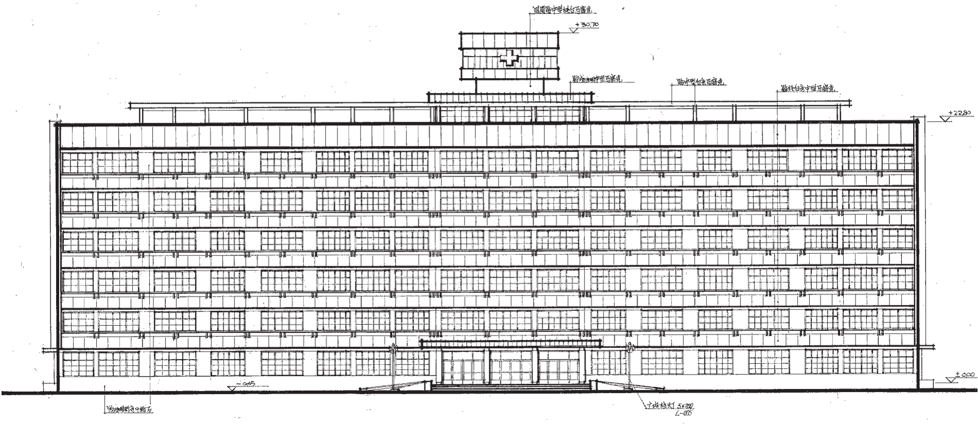
The house is a six-story reinforced concrete structure (partially eight stories). It faces north-south, whose plan shape is rectangular, and the main axis size is 75.30 m×13.80 m. The total floor area of the structure is about 6200 m2, and it is 30.70 m in height. The house was built in the mid-1980s. Fig. 2 is the south elevation of the inspected house, and Fig. 3 is the first-floor plan of the house.
The house adopts a pile foundation composed of 250 precast concrete square piles that are 23 m in length. The design value of the concrete strength is 38 MPa, and the piles are connected with steel-capped sulfuric cement. The design values for the strength of the foundation cap, concrete beams, and other parts are 18 MPa, and that of the concrete materials at the bottom of the main structures is 23 MPa. The stair slabs and the stair beams are made of cast-in-place concrete; the reinforcement bars are of HPB235 and HRB335 types; their diameters are mainly 18 mm, 20 mm, 22 mm, and 25 mm. The thickness of the floor slab is generally 80 mm and 100 mm. The water tank at the top of the house is made of compact concrete and HPB235-type reinforcement bars. The concrete is poured at one time, leaving no construction joints.
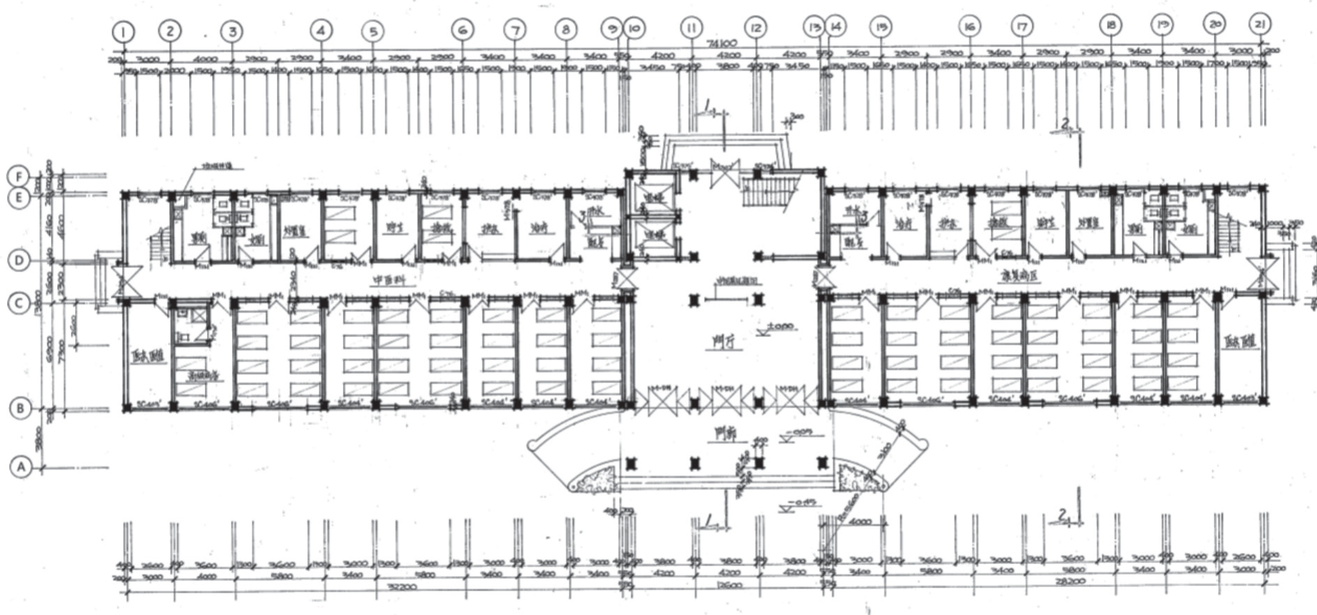
Concrete beams and columns buttress the upper part of the house. The main dimensions of the concrete columns are 250 mm×250 mm, 400 mm×400 mm, 400 mm×500 mm; the main dimensions of the concrete beams are: 150 mm×440 mm, 200 mm×400 mm, 200 mm×720 mm, 200 mm×970 mm, 250 mm×680 mm, 250 mm×720 mm, 250 mm×930 mm. The floor and roof panels are mainly the prestressed concrete perforated slabs, and the slabs in the six stories and some areas (located in the axes of 2-4×D-E, 5-6×D-E, 8-9×D-E, 14-16×D-E, 17-20×D-E, among others) are cast-in-place concrete slabs. The roof adopts SBS waterproof membrane and the three stairs in the house are made of cast-in-place reinforced concrete.
Detection Methods
Macro Detection Methods
(1) Appearance inspection: The inspectors were used to observe the whole house with the naked eye. The surface stucco layer was removed, if necessary, to observe the internal damage. Photos of the existing problems were taken.
(2) Test of the compressive strength of concrete: ZC3-A concrete rebound tester was used to test the strength of the concrete structural members of the house. Specifically, the concrete surface stucco layers of the inspected members were chipped away at until the solid surface was exposed; after handling the surface of the members with a grinding wheel, the rebound value and the carbonization depth were measured with a rebound tester and a carbonization depth gauge, respectively; with the corrected value of rebound angle and the average carbonation depth, the concrete strength of each measured area was calculated, based on which the compressive strength of each member was calculated [26].
(3) Measurement of the overall inclination of the house: According to JGJ 8-2016, the J2-2 theodolite and a steel ruler with a range of 30 mm were used on site to measure the verticality of the walls, in accordance with relevant regulations of the theodolite surveying in deformation measurement [27].
Micro Detection Methods
(1) X-ray fluorescence (XRF)
The X-ray fluorescence spectrometer of ARLADVNT3600 was utilized to detect and analyze the chemical composition of concrete powder, as well as its element content.
(2) Simultaneous thermal analysis (STA)
With a German synchronous thermal analyzer (NETZSCH, STA449F3Jupiter), the thermal properties of concrete powder samples were detected and analyzed with the methods of thermogravimetric (TG) and differential scanning calorimetry (DSC) analysis. The detection was conducted in a nitrogen atmosphere, with the temperature ranging from room temperature to 900ºC, the heating rate being 20ºC/min.
(3) X-ray diffraction (XRD)
The chemical composition of concrete materials was detected and analyzed with a BRUKER DB Advance X-ray diffractometer. With the electrical voltage and current at 40 kV and 40 mA respectively, Cu Kα radiation, λ = 1.5406Å, was diffracted from 7.5° to 42.5°, with a step size of 0.02° and a scan time of 0.1 s/step. Subsequently, a quantitative analysis of XRD measurement results was conducted to figure out the chemical composition using the method of Rietveld.
(4) Scanning electron microscope (SEM)
Regulus 8100 SEM, made by HITACHI, Japan, was used to carry out the test with the electrical voltage at 20 kV. The built-in energy dispersive X-ray spectrometer was utilized to analyze the composition of elements in designated areas.
Results and Discussion
Detection Results and Check on Structural Safety
Foundation
The on-site inspection results showed that there supervened no obvious cracking of the superstructure due to differential settlement.
Superstructure
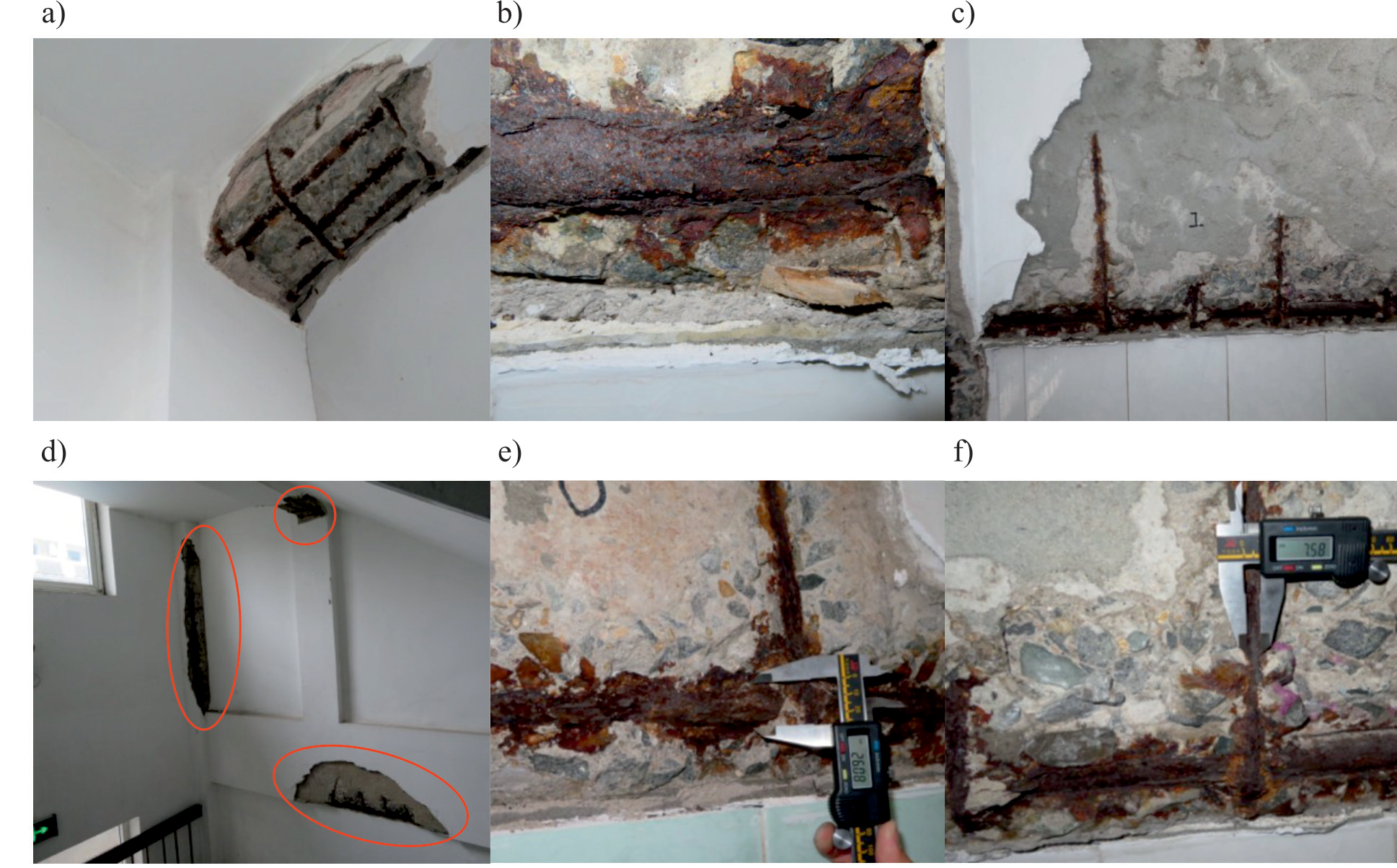
(1) Concrete members: The house is a frame structure with concrete beams and columns as the main load-bearing members. On-site inspection results demonstrated that the concrete protective layers burst and peeled off, and reinforcement bars corroded in several sites inside the house, i.e., the 2×C-E beam, 2×E column and ladder beams on the first to third floors of the west staircase, and 20×C-E beam, 20×E column on the first to fourth floors of the east staircase. Details are shown in Fig. 4. Except for part of the overhanging eaves of the north facade whose concrete was peeled off and reinforced concrete corroded, the rest of the load-bearing members were in normal service.
(2) Floor and roof panels: water seepage occurred on 1st floor 7-8×B-C, 3rd floor 19-20×B-C and 5th floor 19-21×B-C floor panels, computer room, and roof panels of the west staircase.
(3) Walls: water seepage and stucco layers peeling off were serious on the wall axes of 1st floor 1×B-C, 14-15×E, 21×D-E, 3rd floor 21×B-C, 4th floor 1×B-C, and 5th floor 1×E.
Detection Results of Strength and Overall Inclination of Concrete Materials
Detection Results of Strength
A total of 25 concrete beams and columns were randomly selected. The results showed that the age-corrected value of concrete strength was between 19.3 and 29.2 MPa, the average value of concrete strength was 23.5 MPa, and its standard value was 18.6 MPa which was slightly different from the design value. The carbonization depth of all members was greater than 6mm, and more details are shown in Table 1.
Fig. 4.
Various conditions of steel corrosion: a) Corrosion of steel bars in the beam as a whole; b) local corrosion of steel bars; c) corrosion of longitudinal bars and stirrups in beams; d) corrosion of steel bars in beams and columns; e) diameter of longitudinal bars after corrosion; and f) diameter of stirrups corroded.
Detection Results of Inclination
Due to the limitations of the on-site environment, two observation points were set and a total of 4 inclination values were obtained. The inclination from the observation points was 0.3‰ and 1.0‰, which were within the normal range and accorded with the designated limit value specified in Article 7.3.10 of GB 50292-2015 [28]. Detection results are displayed in Table 2.
Micro Detection Results
X-ray fluorescence spectrometer was used to analyze the concrete powder samples, and the chemical elements and oxide composition content were obtained. According to the results, the chemical elements are mainly Calcium (Ca), Silicon (Si), Aluminium (Al), Ferrum (Fe), and others, whose content are similar to those of ordinary concrete. However, it’s worth noting that the Chlorine (Cl) content was up to 1.47%, far more than the 0.06% limit designated in GB 50010-2010 (2015 edition) [29]. Tables 3 and 4 provide more details. The high chlorine content of the concrete may be attributed to the use of sea sand or the close location of the house to the sea.
According to the results of the simultaneous thermal analysis (STA) of concrete powder, the trough around a temperature of 100ºC signaled the heat loss caused by water evaporation inside the concrete, which corresponded to the process of products of cement hydration removing free water. An endothermic peak around 680°C represented the decomposition of CaCO3, and the mass loss embodied the release of CO2. No obvious trough in the TG-DSC curve around 430ºC meant no Ca(OH)2 in the concrete. Detailed results are shown in Fig. 5.
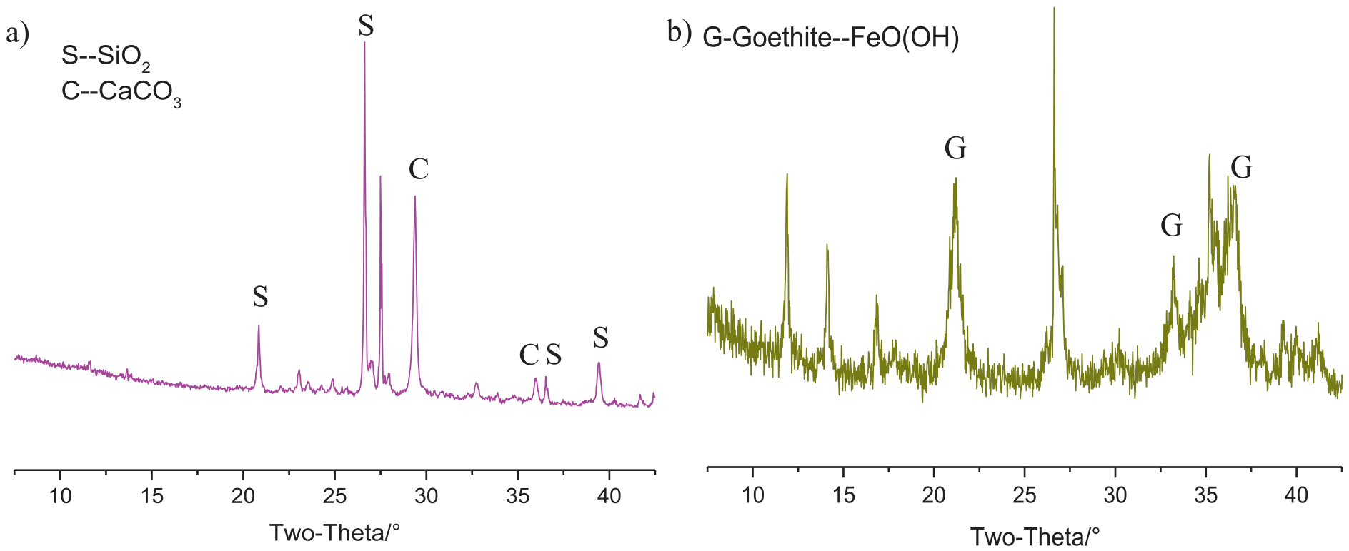
The results gained through XRD analysis also supported the above argument that no Ca(OH)2 existed in the concrete. Ca(OH)2 in the concrete was carbonized into CaCO3 after over 30 years. XRD results in Fig. 6a) illustrated that the chemical composition of concrete materials was mainly SiO2 and CaCO3, and results in Fig. 6b) demonstrated that the main composition of the corroded reinforced concrete powder was rust.
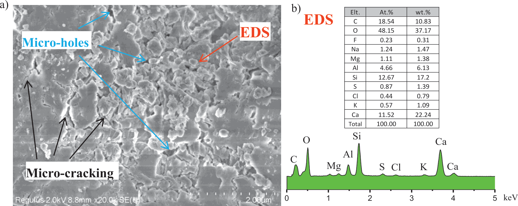
A micro detection of the appearance of concrete samples was conducted with a scanning electron microscope and it’s discovered that there were many micro-cracks and holes on the surface of the concrete samples, and the concrete was partially loose, which may affect the strength of the concrete. Moreover, besides C-S-H gel elements, such as Ca, Si and O, other elements like Al, C, Mg, S, Cl were also discovered in the local area of the concrete samples by virtue of energy spectrometer. The results are shown in Fig. 7.
Table 1.
Test results of compressive strength of concrete members.
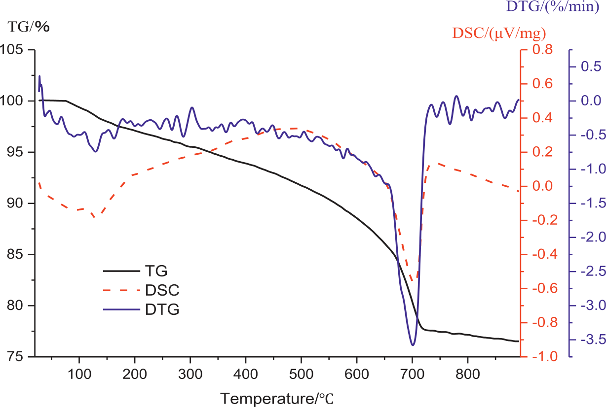
Table 2.
Results of house inclination measurement.
| Location | Height of the house (m) | Degree of inclination (mm) | Ratio of inclination (‰) | Direction |
|---|---|---|---|---|
| 1×B | 17.5 | 5 | 0.3 | West |
| 17.5 | 17 | 1.0 | South | |
| 1×E | 17.5 | 6 | 0.3 | West |
| 17.5 | 5 | 0.3 | South | |
Table 3.
Chemical composition of the powders of concrete in wt.%.
| Ca | Si | Al | Fe | K | Na | S | Mg | Cl | Ti | Others |
|---|---|---|---|---|---|---|---|---|---|---|
| 50.23 | 25.85 | 7.03 | 5.33 | 3.28 | 2.43 | 1.80 | 1.55 | 1.47 | 0.54 | 0.49 |
Check on Structural Bearing Capacity
Establishment of a Computational Model of the Structural Frame
The structural assessment of the house was conducted based on the on-site investigation, functional requirements, and load conditions. To perform the analysis, the structural calculation software PKPM, developed by the CAD Engineering Department of China Academy of Building Research, was utilized. The resulting model, obtained from the software, is shown in Fig. 8.
Establishment of a Computational Model of the Structural Frame
According to GB 50009-2012 [30], the specific dimensions of the members and construction methods, the standard load values of the house are as follows:
(1) Standard load value of floor (precast panel): dead load is 3.0 kN/m2; live load is 2.0 kN/m2; (2) standard load value of floor (cast-in-place panel): dead load is 3.5 kN/m2; live load is 2.0 kN/m2; (3) standard load value of roof (precast panel): dead load is 5.0 kN/m2; live load (overhead roof) is 0.5 kN/m2; (4) standard load value of staircase (precast terrazzo treads): dead load is 6.5 kN/m2; live load is 3.5 kN/m2.
This paper was to analyze the actual compressive bearing capacity of concrete beams and columns, whose strength was designated as 19 MPa based on the on-site investigation results. The structural calculation software PKPM was used to check the bearing capacity and the results showed that the main members in several places (22 sites on the 1st floor, 8 sites on the 2nd floor and one site on the 3rd floor) failed to meet the requirements stated in Article 5.2.2 of GB 50292- 2015 that the ratio of the bearing capacity of concrete structural members to its effect should reach au level. The details are given in Table 5. The bearing capacity of other concrete structural members to its effect reached au level.
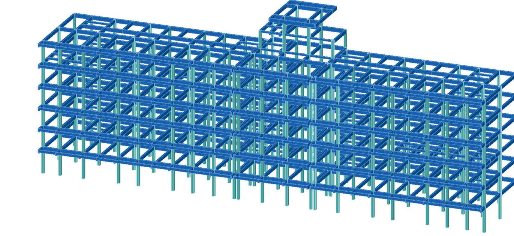
Table 5.
Statistical table of components that do not meet structural verification.
Overall Safety Assessment of the House
Foundation
The on-site investigation revealed that no settlement, deformation or cracks occurred in the house’s superstructure, and the foundation was stable without differential settlement which may affect the main structure. According to Article 7.2.3 of GB 50292-2015, the safety grade of the foundation was rated Au.
Upper Load-Bearing Structures
(1) Rating of load-bearing function of structures
According to Article 7.3.5 of GB 50292-2015, main members and their safety grades were rated below: on the first floor, there are 287 main members, of which 19 concrete columns were rated as the grade of du, 2 concrete columns cu, 5 concrete columns bu, and the other members were rated as au, resulting in the overall safety grade of the first floor of Du; on the second floor, there are 288 main members, of which 13 concrete columns were rated as du and the other members au, so the overall safety grade was Du; on the third floor, there are 309 main members, of which 3 concrete columns were rated as du, 1 concrete column bu, and the remaining members au, so its overall safety grade is Cu; on the fourth floor, there are 295 main members, of which 2 concrete columns were rated as cu, and the rest members au, so the safety grade of the fourth floor was Bu; from the fifth floor to part of the eighth floor, a total of 642 main members were rated as au, so their safety grades were Au .
According to Article 7.3.6 of GB 50292-2015, common members and their safety grades were rated the following: from the 1st floor to part of the 8th floor, a total of 779 common members were rated au grade, so their safety grades were rated Au.
According to Article 7.3.8 of GB 50292-2015, the safety grade of load-bearing function of the structures was rated Du.
(2) Rating of structural integrity
The main structures of the house were constructed in accordance with the design plan. The structural layout was reasonable, and the overall system was complete. The selection of structure typology and the design of force transmission route were accurate and were conformed with national design specifications. However, reinforcement bars corroded, and concrete burst in some concrete beams and columns. According to Article 7.3.9 of GB 50292-2015, the safety grade of the structural integrity was Bu.
(3) Rating of lateral displacement of structures
The detection results showed that the maximum lateral displacement of the outer wall of the house is 25 mm, the wall is 11.2 m in height (H), and the vertex displacement is H/448, less than the lateral displacement limit value of H/200 which determines whether lateral displacement of a structure can be rated Cu or Du, according to Article 7.3.10 of GB 50292-2015. Therefore, the safety grade of the lateral displacement of the structure was rated Bu.
According to Article 7.3.11 of GB 50292-2015, the safety grade of the upper load-bearing structures was rated Du.
The Load-Bearing Part of the Containment System
Water seepage occurred in the outer walls, canopies and gutters of the house. The surface layer of the house was basically intact, and there were several signs of dampness at the foot of the wall. According to Article 7.4 of GB 50292-2015, the safety grade of the load-bearing part of the house containment system was rated Bu.
According to Article 9.1.2 of GB 50292-2015, the overall safety grade of the house was rated Asu, which was lower than the designated Asu grade in GB 50292- 2015, thus significantly affecting the overall load-bearing capacity of the house. Therefore, effective measures must be taken immediately.
Note: Au, Bu, Cu and Du are the safety grades of the sub-system, and Asu and Dsu are the safety grades of the appraiser system.
Conclusions
This study highlights that a reinforced concrete building, originally designed with a working life of 50 years, exhibits significant safety issues after being in service for 35 years. Therefore, we strongly recommend conducting a comprehensive investigation of buildings located in offshore areas to ensure their overall safety.
Despite minimal changes in the strength of the concrete materials, the corrosion of certain reinforcement bars within the concrete is remarkably severe. This can be attributed to the high chloride ion content in the concrete, which may be a result of using sea sand during construction or the proximity of the building to the sea. The corrosion of reinforced concrete poses safety risks to the structural members or even the entire building, necessitating special attention.
On-site inspections, which are both practical and effective for assessing the durability and predicting the service life of concrete structures, allow inspectors to examine the actual stress-bearing conditions of the buildings. This method is commonly employed for durability assessments in the present era. Additionally, microscopic analysis of the chemical composition is vital for understanding the damage mechanisms of buildings. These results help analyze the causes and mechanisms of damage while corroborating relevant macroscopic physical changes.
Durability issues can have a significant impact on the service life of concrete structures, especially in the case of offshore buildings. While durability has gained attention in the design stage of many newly constructed structures, it remains crucial to address the durability problems of in-service buildings. Since different environments and service conditions contribute to various causes of durability issues, it is essential for relevant personnel to be aware of these concerns and seek professional analysis of the causes. This will enable the development of targeted solutions to mitigate the durability problems effectively.