

Introduction
The oldest and most used water treatment process, which constitutes the main part of a treatment plant, is sedimentation. The performance of sedimentation-settling tanks (ST) can have a considerable effect on the other processes of the plant [1]. The task of settling tanks is to remove suspended solids, so their efficiency affects the performance of accompanying parts of the treatment plant [2]. Sedimentation can be thought of as a process that triggers splitting, as referred to in [3], but in the case of photoelectrochemical water splitting to produce clean hydrogen by the conversion of abundant solar energy, whereas in our case for splitting particles from water in a settling tank, an ST is a process where gravity separation of particles is applied. To achieve this gravity separation of particles, the water in the tank should be held long enough on one side, and on the other side, the tank must be designed appropriately [4]. Within a settling tank, particle settling is often reduced by both short-circuiting and turbulence [5], which occur due to the circulation zone in the sedimentation layer. The existence of a circulation zone results in lower tank efficiency, diminishing the performance of the ST [6], reducing the effective volume of the tanks, and creating regions with high turbulence intensity, causing the resuspension of particles [7-8]. The main principle of the ST is to reduce the flow velocity in order to allow the majority of suspended particles to settle down in the tank. Uniform and calm flow in the tank facilitates particle deposition at a constant velocity in a shorter time [8].
In general, the settling of the majority of the particles to the bottom of the basin is influenced by the geometry of the tank, which also affects the hydraulic detention time as well as the flow field into the tank. To avoid the formation of recirculation zones in the tank, the appropriate design of ST should be carefully considered [7]. The performance of the ST can be improved through baffle utilization as a geometrical modification of the ST. Baffles help overcome the velocity gradient, dead zones, and short-circuiting, increasing the aspect ratio of the tank [4]. However, the use of baffles without proper investigation could result in worse tank performance than without a baffle. Therefore, it is essential to study the optimal position and size of the baffle for the specific settling tanks [9].
Baffles in Settling Tanks
The use of baffles has gained particular attention as a solution for particle settling in settling tanks (ST) (Fig. 1). It is important to note that baffles should never be placed in ST where they would cause serpentine flow (180◦ turns) because the turbulence caused by abrupt turns will significantly reduce particle settling [4]. If baffles in the ST are improperly positioned or have an incorrect height, the particle removal performance would be drastically decreased [9].
A large number of studies have been carried out to show the effect of baffle utilization on the hydraulic and treatment performance of settling tanks [6-8, 11-15].
This paper summarizes the current knowledge by providing an overview of the literature on ST performance using baffles. Additionally, the paper offers several recommendations on how to increase the settling efficiency based on factors such as sediment concentration in the inlet zone of ST, location, position, number, and height of the baffle. The intended audience of the review is the general designer of treatment plants, specifically those involved in designing STs.
Materials and Methods
Several research papers have highlighted the potential benefits of using baffles in settling tanks (STs). These studies cover a variety of baffle utilizations in STs. The content of the selected works is mapped by extracting information using the following questions: – What is the aim of the studies? – What are the dimensions of the settling tank? – What approach (method) is used? – What kind of model is used for that approach? – How many baffles are used in the studies, and what
is their location, position, and height? – How does the author describe the accuracy of the
study results?
The Aim of The Studies
In general, this paper includes works that assess the effect of baffles on the efficiency of settling tanks [4]. More concretely, works examine the efficiency of baffle location, configuration, and position, as well as the efficiency of the number of baffles on the flow hydrodynamics and clarification. Some works analyze velocity profiles, kinetic energy, circulation zone, and solids removal efficiency in the ST, comparing for: – The best distance for a single, double, or grid baffle
with the unchanged or changed height of the baffle,
from the inlet of the settling tank. – The best angle of the baffle depends on the inlet
concentration of suspended solids – As well as evaluating if: – The longitudinal baffle affects the turbidity removal
efficiency. – Several baffles influence the performance of the
settling tank.
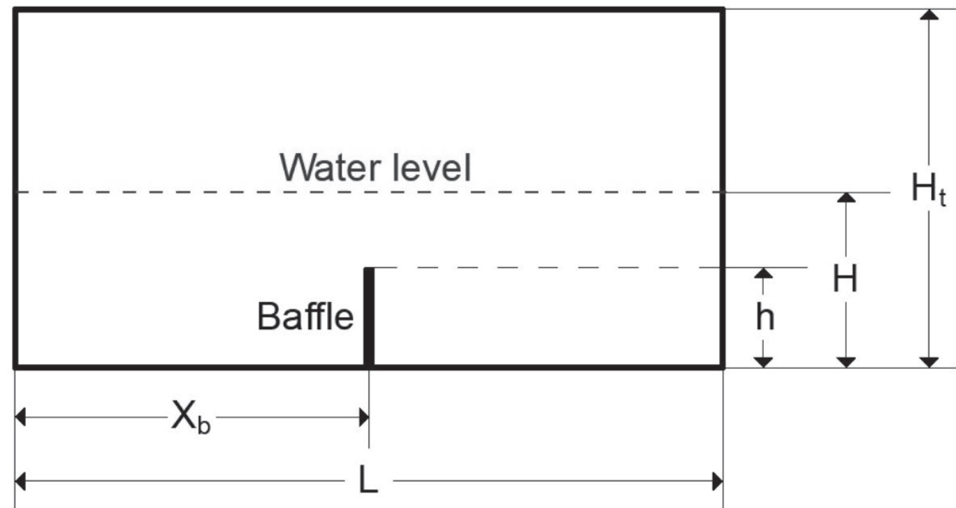
Dimensions of Settling Tanks Used for Studies
As [4] points out, one of the design criteria of rectangular horizontal-flow settling tanks (ST) to minimize short-circuiting in general is that they should be long, narrow, and relatively deep. The sedimentation process in all reviewed studies takes place in a rectangular open channel with different dimensions. The criterion regarding the dimensions of the STs is also applied in all studies. With the exception of one work that used a full-scale settling basin, the other works have used small-scale tanks for the experiments to analyze the effect of the baffle on hydraulic performance and solid removal.
Approaches and Models Used for Studies
Finding new and useful methods to increase the efficiency of sedimentation is the objective of many theoretical, experimental, and numerical studies. In this study, the inclusion of experimental, numerical, and combined studies (experimental and numerical) is presented to examine the effects of baffles on velocity profiles, kinetic energy, circulation zone, and solids concentration in settling tanks (STs). For studying the effects of different inlet positions on the flow field and the efficiency of ST, or to determine the suitable baffle position in ST, models such as the Acoustic Doppler Velocimeter (ADV), Volume of Fluid (VOF), Computational Fluid Dynamics (CFD), Flow-Through Curves (FTCs), k-ε turbulence model (Flow-3D®), Particle Tracking Method (PTM), and 2D numerical model are used. Some studies also analyze the reduction of turbidity and suspended matter through water monitoring in STs using turbidity sensors and grab samples.
Types of Baffles and Their Dimensions
In the reviewed works, baffles are of different types: single, double, double-perforated, containing two slotted baffles, and in combination with the screen. The baffles’ location varies for different works. They are located at different distances from the inlet. The vertical, horizontal (laying across the width of the channel, or longitudinally), and angled positions of baffles are analyzed. Some works examine the efficiency of the sedimentation process using: a) one height of the baffle in one baffle location; one height of the baffle in different baffle locations; different heights in different locations; and one height of the baffle in different baffle angles, as well as several baffles in the different locations with one height.
Table 1.
A summary of the content of reviewed studies.
(Table 1) provides an overview of the content of reviewed studies in terms of their objectives, water flow, particle concentration, baffle types, baffle dimensions, and locations. The conclusions of the reviewed papers regarding the impact of baffles on the performance of settling tanks are summarized in (Table 2).
The Accuracy of The Work’s Results
Several works reviewed in this paper highlight whether the results obtained from the research can be considered accurate. To achieve this, some researchers have conducted repetitive experiments under identical conditions to verify the quality and accuracy of the collected data.
Results and Discussion
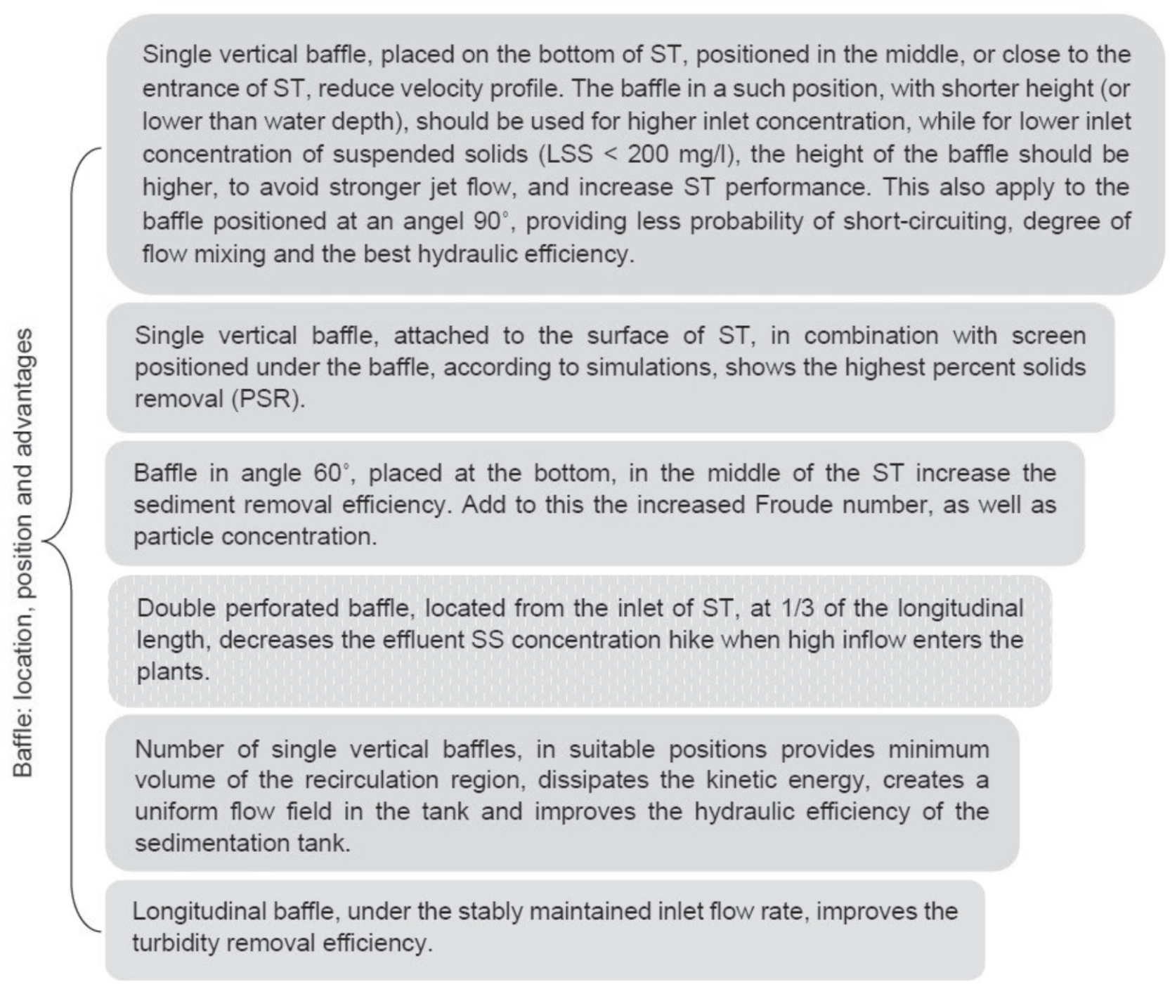
The reviewed papers in general emphasize that settling tank (ST) performance will be improved if baffles are placed in the basin. However, the efficiency of the tank’s performance using baffles depends on various factors, such as the sediment concentration in the inlet zone of ST, and the type, location, position, number, and height of the baffle. Placing baffles in the ST, the uniform flow field occurs, the kinetic energy dissipates, the minimum volume of the recirculation region is provided, and the hydraulic efficiency of the ST will be improved. A great contribution to achieving these results is the location, position, number, and height of the baffle(s). However, works start with a defined inlet sediment concentration, inlet flow rate, or water depth, as well as with a defined tank design. Finally, a narrative summary of the results obtained by reviewing papers is presented in (Fig. 2).
Settling tanks (ST) are commonly used as water and wastewater treatment units in many treatment plants. Their task is to remove suspended particles by holding enough water in the tank. Does ST provide sufficient flow velocity to allow the major suspended particles to settle down? It is known that it depends on the geometry of the tank. The answer to this question is provided in this review paper. The review shows that the ST alone cannot consistently meet hydraulic and treatment performance requirements without interfering with its geometry. When combined with a baffle in its design, the hydraulic and treatment efficiency of the ST can be improved.
Table 2.
The results of the reviewed studies.
Conclusions
In this paper, a range of works has been analyzed to provide an overview of the effects of baffles on settling tanks (ST). In general, it was observed that baffled ST showed better results than ST without baffles. Hence, before using a baffle for ST, the following recommendations should be taken into consideration:
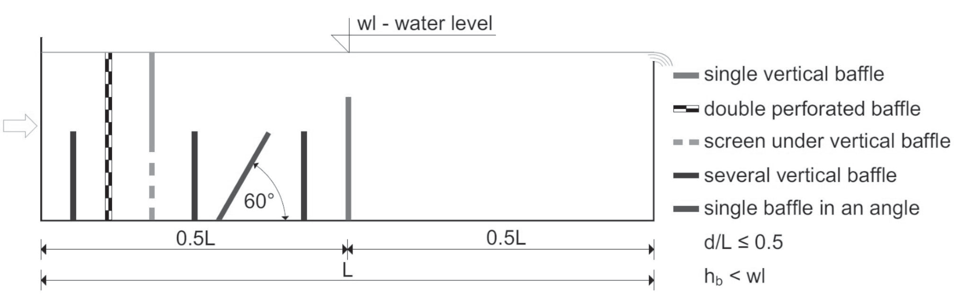
If a single vertical baffle is used, it should be placed on the bottom, in the middle, or close to the entrance of ST, with a height lower than the water depth. For cases with high inlet concentrations, the baffle should have a shorter height.
If a double-perforated baffle is used, it is better to locate it close to the inlet of ST (at the first half of the ST length).
To achieve a high solid removal percentage, the screen should be positioned under the baffle attached to the surface of ST.
When using several vertical baffles placed on the bottom of ST, positioned at a suitable distance from the inlet as well as from each other, they should be located in the first half of the tank’s length.
If the baffle is placed in an angle position, the best angles are 60˚ and 90˚ compared to 30˚, 45˚, 100˚, 120˚, and 150˚ for a high concentration of suspended solids (SS) and a high Froude number (at the limit of smaller than 1).
The recommendations are depicted in (Fig. 3), each using a distinct color.
All of these recommendations are aimed at improving the performance of the ST. This includes improving the flow pattern and solid reduction process. However, the performance of the ST, even when baffles are used, can still be affected by the size of the input suspended solids and the uniformity of flow.
Further studies may be needed to evaluate and compare simulated and experimental results, as well as to ensure the accuracy of the models used for analysis. Furthermore, the design of a settling tank in which all recommendations derived in this paper will be analyzed within the framework of suspended solids reduction is foreseen for the future.