

Introduction
The purification of in-vehicle air pollution mainly involves two aspects: internal pollutants and external pollutants [1-3]. With the comprehensive purification features of modern vehicles, it has become possible to clean impending and existing pollutants in cabins, thereby increasing overall air quality. In recent years, the shift toward intelligent, green, and health-oriented automotive products has made in-vehicle air pollution purification a significant concern for consumers during the selection process [4]. Survey data have indicated that 90% of prospective buyers inquire about air purification functionalities when purchasing a vehicle [5].
In response to this heightened consumer awareness, automotive manufacturers have introduced a variety of products with superior active air quality control and purification capability. For example, SAIC Motor Corporation Limited (abbreviated as SAIC Motor) has developed an active purification health chamber featuring a high-efficiency particulate matter (abbreviated as PM) 2.5 cabin air filtration system and Ultra-Violet C radiation deep ultraviolet disinfection. It aims to provide medical-grade protection for the air conditioning systems of vehicles. Similarly, IM Motors Technology Co., Ltd., has incorporated an active air purification system that monitors environmental pollution, automatically adjusting the air conditioning system of vehicles to manage airflows while stabilizing odor levels. This system also integrates ionizer technology, using an activated carbon health filter and real-time PM2.5 monitoring in the cabin to actively release negative ions that combine with particulate matter, dust, and formaldehyde. In addition, the Model Y of Tesla Inc. includes a bioweapon defense mode equipped with high-efficiency activated carbon and fine HEPA filters, which can effectively trap toxic gases and ultrafine particles [6].
Observations have shown that the diversity of air pollutants in vehicles has led to many approaches to active purification capability, each targeting different pollutants [7]. However, many descriptions of the effectiveness of automotive products lack standardized benchmarks and practical operating conditions, raising concerns about authenticity. These factors make the assessment of in-vehicle pollution purification capabilities complex and the evaluation of the impact of purification technologies on in-car air quality challenging.
The core issue behind these challenges is the lack of a unified definition of in-vehicle pollution purification capability in the automotive industry. Current evaluation methods for such capabilities are inconsistent and lack correlation with actual vehicle operating conditions, limiting the accuracy of evaluation. Evaluation on the purification capability of vehicle pollutants include several key factors: (1) Removal efficiency of pollutants: a main criterion for assessing purification capability is to measure and evaluate the efficiency of removing toxic and harmful gases from cabin air by monitoring the concentration variability of pollutants in the vehicle interior; (2) Filter performance: the basic indicators for evaluating filter performance include filtration efficiency of particulate matter and gas, service life, and maintenance costs [8, 9]; (3) Odor elimination effectiveness: the efficiency of vehicle purification systems can be assessed through subjective assessment and objective measurements of odor removal; (4) System stability and reliability: evaluating the purification capability must also consider system stability and reliability under different pollution conditions to ensure consistent performance and passenger health protection [10].
This comprehensive approach is critical for effectively demonstrating the ability of automotive products in internal pollution purification, facilitating product optimization and upgrading, guiding technological advancements, and promoting high-quality development in the industry. This study mainly focuses on pollutant removal rates and system stability and reliability. Different typical pollution scenarios are simulated to evaluate the purification capabilities of vehicle pollutants based on specific operating conditions and testing methods.
Materials and Methods
Requirements for Testing Vehicles
Seven vehicles claiming to have different purification capabilities were selected as the test subjects, and relevant configurations are shown in Table 1. These seven models should also meet the following criteria: a maximum of nine seats, including the driver’s seat; the air conditioning system must be fully operational and able to switch manually between internal and external circulation modes.
The vehicles were equipped with an active air purification system, which has not been disassembled or modified except for replacing the filter element. The active air purification system can work normally, and the filter element can be replaced. The air conditioning system can work normally and can be manually switched between internal and external circulation modes.
Table 1.
Interior purification function configurations of the 7 test vehicle models.
Requirements for Testing Devices
The primary requirements for the testing apparatus are as follows:
(1) The testing cabin of the whole vehicle can accommodate the entry of the vehicle to be tested, and the minimum gap between the vehicle to be tested and the whole vehicle testing cabin is 1.5 m. The minimum gap between the top of the vehicle to be tested and the whole vehicle testing cabin is 2 m;
(2) The testing cabin is equipped with an air purification device and a constant temperature and humidity device;
(3) The testing cabin is equipped with lighting equipment – a movable irradiation surface light panel (1000 W);
(4) The testing cabin instrument can perform PM10/PM2.5 detection, carbon monoxide (abbreviated as CO) / sulfur dioxide (abbreviated as SO2) / nitrogen dioxide (abbreviated as NO2) detection, and total volatile organic compound (abbreviated as TVOC) detection;
(5) The vehicle testing cabin is equipped with devices for generating or introducing particulate pollutants or gas pollutants, as well as circulating fans and mixing fans;
(6) There are 5 recording points inside the tested vehicle and 6 recording points outside the tested vehicle.
The main detection instruments involved are shown in Fig. 1.
Parameters and Description
Description of General Requirements
(1) There are 5 recording points inside the tested vehicle and 6 recording points outside the tested vehicle;
(2) The maximum number of members (at least 5) was recorded as the number of points inside the vehicle, with the detection point located in the range of the passenger’s head during normal driving. The external recording points were located at the front, rear, left front door, left rear door, right front door, and right rear door;
(3) The test vehicle had a first state and a second state: in the first state, the doors, windows, rear trunk, and sunroof of the test vehicle were all open; in the second state, the doors, windows, rear trunk, and sunroof of the tested vehicle were all closed;
(4) The first preset condition was that the temperature was in the first temperature range (23±5ºC). The relative humidity was in the first relative humidity range (50%±10% RH), and the concentration of particulate pollutants was in the first concentration range;
(5) The second preset condition was that the temperature was in the first temperature range; the relative humidity was in the first relative humidity range; the concentration of particulate pollutants was in the first concentration range, and the TVOC concentration was less than or equal to the preset concentration (200 μg/m3);
(6) The first concentration range of particulate pollutants is as follows: a PM10 concentration less than or equal to 50 μg/m3, and a PM2.5 concentration less than or equal to 35 μg/m3. The second concentration range was maintained at 2500±500 μg/m3 for PM10 and PM2.5;
(7) The first preset duration was 20 minutes, and the second preset duration was 15 minutes.
(8) Preprocessing method: The air purification device, constant temperature and humidity device, mixing fan, and circulating fan were turned on to ensure that the vehicle test chamber reaches the first preset condition. The tested vehicle was placed inside the test chamber that has reached the first preset condition and maintained for the first preset duration.
Main Parameter Description
(1) n: number of recording points under test;
(2) internal: refers to the interior of the car;
(3) External: refers to the exterior of the car;
(4) PMx: either PM2.5 or PM10;
(5) ∧: denotes the conjunction relationship;
(6) ∨ denotes the disjunction relationship.
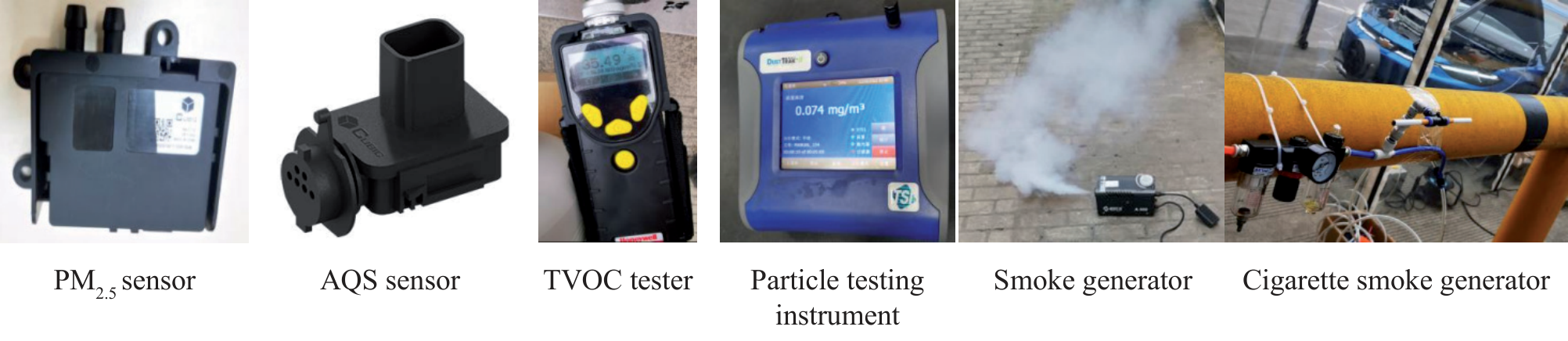
Table 2.
Test scenarios and working conditions.
Experimental Methods
The purification capability of a vehicle for pollutants is evaluated in three modes, reflecting different pollutant types and overall vehicle conditions:
(1) Mode 1 (Parking Mode): Assess the vehicle’s ability to act as a barrier against particle pollutants;
(2) Mode 2 (Normal-Temperature Driving): Evaluate the vehicle’s purification capacity for particle pollutants during normal driving. This mode can be further divided into multiple scenarios according to different vehicle usage patterns and pollutant sources;
(3) Mode 3 (Normal temperature driving condition): This mode focuses on the ability of vehicles to purify gaseous pollutants and can also be divided into several operational scenarios depending on usage and pollutant sources.
The testing and calculations conducted in these three modes result in indifferent purification values, which can be obtained through specific methods to accurately reflect the effectiveness of vehicles in purifying pollutants under different environments.
This experimental method considers the entire operating environment and driving conditions of vehicles, simulating and assessing their ability to purify pollutants under different pollutions. The actual purification capability can be comprehensively and accurately calculated by considering real-world pollutions experienced by the tested vehicle. This methodology addresses a key gap in pollutant purification testing, enabling users to better understand the purification abilities of their vehicles and make informed decisions about vehicle choice. The main Experimental Methods involved are shown in Table 2.
Mode 1 (Parking Mode): the Ability of Vehicles to Block Particulate Pollutants
This mode is used to evaluate the ability of vehicles to block particulate pollutants under static conditions [11].
The pollution scenarios and vehicle operating conditions are set as shown in Table 3.
Key testing steps are as follows:
(1) The vehicle was introduced into the test chamber. All doors, windows, the trunk, and the sunroof were opened. The purification system and the temperature and humidity control system were activated. The mixing and circulation fans were turned on to ensure the cleanliness, temperature and humidity in the test chamber meeting the following standards: the vehicle was allowed to remain stationary for 20 minutes, with a temperature of 23±5ºC, a relative humidity of (50±10%) RH, a PM10 concentration of ≤50 μg/m³ and a PM2.5 concentration of ≤35 μg/m³.
(2) The filtration system, constant temperature, and humidity system of the experimental cabin were maintained to close all doors and windows and keep the mixing fan and circulating fan operating for 15 minutes. The maximum number of the detection points of particle pollutant concentration in the vehicle (at least 5) was set in the range of passengers’ heads. The concentrations of particulate pollutants in the vehicle were continuously detected in the last 5 minutes and recorded as ZnPMx, internal0. The average concentration is calculated as follows:
(1)
Table 3.
Test scenarios and working conditions.
(3) The filtration system, constant temperature, and humidity system of the experimental cabin were turned off to start the particle generator of the test cabin and keep the mixing fan and circulating fan working. The smoke was introduced into the experimental cabin through the duct. The PM2.5 concentration in the experimental cabin was maintained in the range of 2500±500 μg/m3 for 120 minutes to continuously detect the concentration of particulate pollutants in the car in the last 5 minutes, denoted as ZnPMx, internal15. The average concentration is calculated as follows:
(2)
(4) Based on the above two average concentration values, the barrier properties of the entire vehicle are calculated as follows:
Mode 2 (Driving Conditions at Normal Temperature): the Purification Capacity for Particle Pollutants During Normal Driving
The ability of the vehicle to purify particle pollutants is tested and evaluated under four different pollutions: A, B, C, and D.
Conditions A: Scenarios of Sandstorm Pollution
The settings for the pollution scenarios and vehicle operating conditions are presented in Table 4.
The key testing steps are as follows:
(1) The vehicle to be tested was put in the testing compartment, making it in the first state. The air purification device, constant temperature and humidity device, mixing fan, and circulating fan were turned on to obtain the first preset condition in the vehicle testing chamber. The test vehicle was placed in the vehicle testing chamber for the first preset duration, which was 20 minutes in this embodiment. The air purification device and the constant temperature and humidity device were turned off to put the tested vehicle in the second state and start the dust particle generator. When the concentration of PM2.5 and PM10 in the test cabin of the entire vehicle reached and stabilized within the second concentration range, the dust particle generator was turned off to adjust the purification system of the tested vehicle to working mode. Then, the working mode of the air conditioner was adjusted to external circulation and maintained at the maximum power for a fourth preset duration, which was 100 minutes in this embodiment. After that, the purification ability of the tested vehicle in an external sandstorm environment was simulated.
(2) The PM concentrations of all recording points outside the tested vehicle for 10 minutes were obtained and recorded as ZnPMx, external1. The average concentration is calculated as follows:
(4)
Table 4.
Test scenarios and working conditions.
(3) At the same time, the PM concentrations of all recorded points in the tested vehicle for 10 minutes were obtained and denoted as ZnPMx, internal1. The average concentration is calculated as follows:
(5)
(4) Based on the above two average concentrations, the particulate matter purification capacity of the entire vehicle under condition A is calculated as follows:
(6)
Conditions B: External Smoking Pollution
The pollution and vehicle operating conditions are set as shown in Table 4.
Key testing steps are as follows:
(1) The vehicle to be tested was placed in the vehicle testing compartment, making it in the first state. The air purification device, constant temperature and humidity device, mixing fan, and circulating fan were turned on to obtain the first preset condition in the vehicle testing cabin. The tested vehicle was placed in the vehicle testing cabin for the first preset duration. The air purification device, constant temperature, and humidity device were turned off, and the tested vehicle was placed in the second state. The oil fume particulate matter generator outside the vehicle testing cabin was started, and the oil fume particulate matter was injected into the vehicle testing cabin. When the concentration of PM2.5 and PM10 in the vehicle testing cabin reached and stabilized in the second concentration range, the oil fume particulate matter generator was turned off. Then, the purification system of the tested vehicle was adjusted to working mode, and the air conditioning working mode was adjusted to external circulation and maintained at the maximum power for the fourth preset duration. The preset duration in this embodiment was 100 minutes, which was used to simulate the purification ability of the tested vehicle in a smoke exhaust environment.
(2) The PM concentrations of all recording points outside the tested vehicle for 10 minutes were obtained and recorded as ZnPMx, external2. The average concentration value is calculated as follows:
(7)
(3) The PM concentrations of all recorded points in the tested vehicle for 10 minutes were obtained and denoted as ZnPMx, external2 . The average concentration is calculated as follows:
(8)
(4) Based on the above two average concentrations, the particulate matter purification capability of the entire vehicle under condition B is calculated as follows:
(9)
Conditions C: Internal and External Oil Fume Pollution, External Circulation
The pollution scenarios and operating conditions are set as shown in Table 5.
Key testing steps are as follows:
(1) After the vehicle enters the vehicle test chamber, the vehicle to be tested was placed in the first state. The air purification device, constant temperature and humidity device, mixing fan, and circulating fan were turned on to make the vehicle test chamber reach the first preset condition. The vehicle to be tested was left to stand in the vehicle test chamber for the first preset time. Then, the air purification device and constant temperature and humidity device were turned off. The oil fume generator in the vehicle test chamber was started, and specific particulate pollutants were injected into the vehicle test chamber. Under condition C, the specific particulate pollutants were high-pollution oily particles. The vehicle to be tested was still in the first state, and the mixing fan and circulating fan continued to work. When the concentration of oil fume particles PM2.5 and PM10 in the vehicle test chamber reached and stabilized at the second concentration range, the oil fume generator was turned off, and the tested vehicle was placed in the second state. When placing the purification system in working mode, the working mode of the air conditioner was adjusted to external circulation and maintained at the maximum power for the fifth preset duration. It was 30 minutes in this embodiment, and the internal pollution of the tested vehicle and the purification capacity of external circulation pollutants can be simulated.
Table 5.
Test scenarios and working conditions.
(2) The PM concentrations of all recording points outside the tested vehicle for 10 minutes were obtained and recorded as ZnPMx, external3. The average concentration is calculated as follows:
(10)
(3) The PM concentrations of all recorded points within the tested vehicle for 10 minutes were obtained and denoted as ZnPMx, internal3. The average concentration is calculated as follows:
(11)
(4) Based on the above two average concentration values, the particulate matter purification capability of the entire vehicle under condition C is calculated as follows:
(12)
Conditions D: Internal and External Oil Fume Pollution, Internal Circulation Scenarios
The pollution scenarios and vehicle operating conditions are set as shown in Table 5.
Key testing steps are as follows:
(1) After the vehicle enters the vehicle test chamber, the test vehicle was placed in the first state. The air purification device, constant temperature and humidity device, mixing fan, and circulating fan were turned on to make the vehicle test chamber reach the first preset condition. The test vehicle was then left to stand in the vehicle test chamber for the first preset time. When the accumulated time reached the first preset time, the air purification device, constant temperature, and humidity device were turned off. The oil fume generator in the vehicle test chamber was started, and the oil fume particles were injected into the vehicle test chamber. When the concentration of oil fume particles PM2.5 and PM10 in the test chamber reached and stabilized in the second concentration range, the oil fume generator was turned off to put the test vehicle in the second state. The working mode of the air conditioner was adjusted to internal circulation and maintained at the maximum power for the fifth preset duration. The fifth preset duration was 30 minutes in this embodiment.
(2) The PM concentrations of all recording points outside the tested vehicle for 10 minutes were obtained and recorded as ZnPMx, external4. The average concentration is calculated as follows:
(13)
(3) The PM concentrations of all recorded points within the tested vehicle for 10 minutes were obtained and denoted as ZnPMx, internal4. The average concentration is calculated as follows:
(14)
(4) Based on the above two average concentrations, the particulate matter purification capacity of the entire vehicle under condition D is calculated as follows:
(15)
Particulate Pollutant Purification Capacity of the Entire Vehicle
Based on the purification values of conditions A, B, C, and D, the particle polish purification capability of the entire vehicle can be calculated as follows:
Mode 3 (Driving Conditions at Normal-Temperature): the Purification Capacity for Gaseous Pollutants during Normal Driving
The ability of the vehicle to purify pollutants under three different gas pollutions: E, F, and G, was tested and evaluated.
Condition E: Automotive Exhaust Pollution Scenario
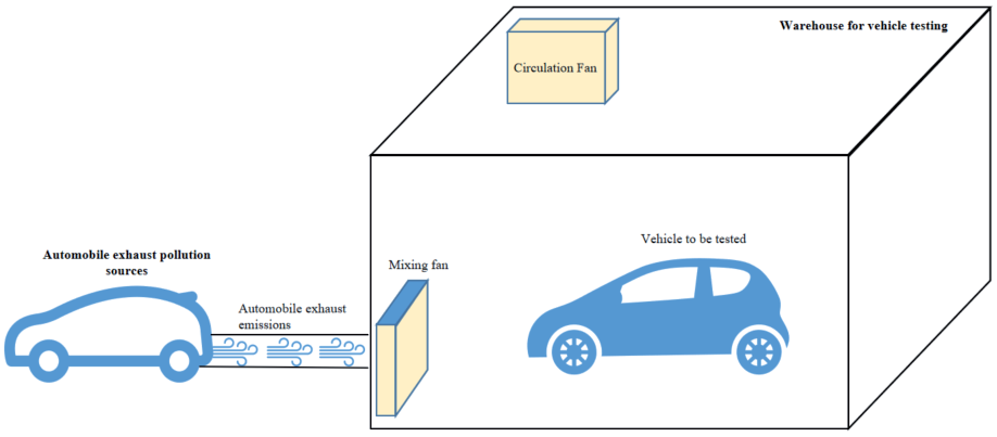
The specific details of condition E are shown in Table 6, and a schematic diagram of the testing device is shown in Fig. 2.
Key testing steps are as follows:
(1) The test vehicle was placed in the vehicle testing compartment, with the test vehicle in the first state. The air purification device, constant temperature and humidity device, mixing fan, and circulating fan were turned on to make the vehicle testing compartment reach the first preset condition. The test vehicle was placed in the vehicle testing compartment for the first preset time. The test vehicle was connected to the hub, thereby connecting the exhaust tailpipe of the test vehicle to the vehicle testing compartment. The air purification device and constant temperature and humidity device were tuned off to make the test vehicle in the second state and control the test vehicle at the highest speed. After maintaining for 10 minutes, the purification system of the test vehicle was adjusted to working mode and turned on the air conditioning. The mode was adjusted to the external loop and maximum power to start timing and maintain the seventh preset duration. The seventh preset duration in this embodiment was 10 minutes, and the purification ability of the vehicle under road exhaust was simulated. The harmful gases contained in car exhaust mainly include SO2/sulfur dioxide and NO2/ nitrogen dioxide.
Table 6.
Test scenarios and working conditions.
(2) The test vehicle was connected to the hub to connect the exhaust tailpipe of the test vehicle to the vehicle testing compartment. The air purification device, constant temperature, and humidity device were turned off to ensure that the test vehicle was in the second state and at the highest speed. After maintaining for 10 minutes, the purification system of the test vehicle was adjusted to working mode, and the air conditioning system was turned on. The mode was adjusted to the external loop and the maximum power to start timing and maintain for 10 minutes;
(3) The concentrations of gas pollutants at all recording points outside the tested vehicle for 10 minutes were obtained and recorded as Zngas, external1. The average concentration is calculated as follows:
(17)
(4) The concentrations of gas pollutants at all recording points inside the tested vehicle for 10 minutes were obtained and denoted as Zngas, internal1. The average concentration is calculated as follows:
(5) Based on the above two average concentration values, the purification capacity of the entire vehicle for gas pollutants under automobile exhaust pollution can be calculated as follows:
(18)
Condition F: Industrial Waste Gas Pollution Scenarios
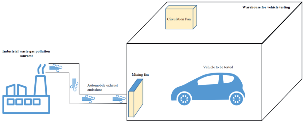
The ability of the vehicle to purify pollutants through external circulation under simulated industrial waste gas pollutions is shown in Table 7. It also details the pollution scenarios and vehicle operating conditions.
The specific details of test condition F are shown in Table 7, and a schematic diagram of the testing device is shown in Fig. 3.
Key testing steps are as follows:
(1) The vehicle to be tested was placed in the vehicle testing compartment, with the vehicle in the first state. The air purification device, constant temperature and humidity device, mixing fan, and circulating fan were turned on to achieve the first preset condition in the vehicle testing compartment. The vehicle to be tested was placed in the vehicle testing compartment for the first preset time. The vehicle testing compartment was connected to the pollution source generator with a connecting pipe to introduce the industrial waste gas generated by the pollution source into the vehicle testing compartment. The air purification device, constant temperature, and humidity device were turned off to put the vehicle in the second state. The pollution source generator was turned on to remove SO2. The industrial exhaust gas of NO2 was introduced into the vehicle testing chamber and maintained for 10 minutes. The purification system of the tested vehicle was adjusted to working mode, and the air conditioning system was adjusted to external circulation and maximum power. The timer is started and maintained for 10 minutes to simulate the purification capacity of the vehicle in an industrial exhaust gas environment.
(2) The concentrations of gas pollutants at all recording points outside the tested vehicle for 10 minutes were obtained and recorded as Zngas, external2. The average concentration is calculated as follows:
(20)
(3) The concentrations of gas pollutants at all recording points inside the tested vehicle for 10 minutes were obtained and denoted as Zngas, internal2. The average concentration is calculated as follows:
(21)
(4) Based on the above two average concentrations, the purification capacity of the entire vehicle for gas pollutants under automobile exhaust pollution can be calculated as follows:
(22)
Table 7.
Test scenarios and working conditions.
Condition G: High-Temperature Exposure Pollution Scenario
The simulation assesses the capability of the vehicle to circulate and purify pollutants inside the cabin after exposure to high temperatures. The pollution and vehicle operating conditions are shown in Table 8.
Key testing steps are as follows:
(1) The vehicle to be tested was placed in the vehicle testing compartment, keeping it in the first state. The air purification device, constant temperature and humidity device, mixing fan, and circulating fan were turned on to make the vehicle testing compartment reach the second preset condition. The vehicle to be tested was placed in the vehicle testing compartment for the first preset duration, and the test vehicle was placed in the second state. The air purification device, constant temperature and humidity device, mixing fan, and circulating fan were turned off and the movable irradiation panel light (1000W) was turned on to vertically irradiate the four directions of the test vehicle, namely, the front windshield, left side glass, right side glass, and rear windshield. The vertical distance between the movable irradiation panel light and the glass was 50 centimeters, maintained for 4 hours.
(2) The TVOC detector was opened, and the concentrations of TVOC at each recording point inside the tested vehicle for 5 minutes were obtained and recorded as ZnTVOC, internal1. The average concentration is calculated as follows:
(23)
(3) The vehicle under test was still in the second state. The interior purification system was set to work mode, and the air conditioning system was adjusted to internal circulation with the maximum power for 10 minutes;
(4) The concentrations of TVOC at each recording point inside the tested vehicle for 5 minutes were obtained and recorded as ZnTVOC, internal2. The average concentration is calculated as follows:
(24)
(5) The total volatile organic compound (TVOC) purification capacity of the entire vehicle after exposure to high temperatures is calculated as follows:
Table 8.
Test scenarios and working conditions.
Gas Pollutant Purification Capacity of the Entire Vehicle
Based on the calculation results from the above three scenarios, the toxic and harmful gas purification capacity of the entire vehicle can be calculated as follows:
Comprehensive Pollutant Purification Capacity of the Entire Vehicle
Based on a standard cycle of 12 hours, the vehicle was set to be in a stationary state for 6 hours, with a time weight of 0.5. The time for treating particulate pollutants in the entire vehicle was 3 hours, with a time weight of 0.25. The time for the entire vehicle to handle toxic and harmful gases was 3 hours, with a time weight of 0.25. The comprehensive purification capability of the entire vehicle is calculated as follows:
Results and Discussion
Barrier Capacity
The barrier performance of an entire vehicle against pollutants is related to the body structure, sealing performance, filtration system, emission system, and sealing performance of windows and doors [12]. The corresponding barrier performance scores for the 7 tested vehicles in this experiment are shown in Table 9. Within 15 minutes, the vehicles showed relatively good barrier performance against high-concentration particulate pollutants from outside, with 86% of the vehicles receiving full marks. This indicates that most vehicle models have good barrier performance, excellent structural design, and high manufacturing levels. However, this experiment did not examine the overall barrier performance of the vehicle over a long period of time, making it impossible to evaluate the vehicle’s barrier performance against pollutants over an extended period. Future research will continue to optimize the testing and evaluation methods.
PM Purification Capacity
After testing and calculation, the particulate matter purification capability and comprehensive particulate matter purification capabilities of the 7 vehicles under different pollutions are shown in Table 10. Due to the lack of a PM2.5 filtering device, the fifth vehicle exhibited average particulate matter purification capability under different operating conditions. All other models were equipped with PM2.5 filtration devices, which can effectively purify particulate matter under external circulations. However, different PM2.5 filtration devices may have different filtration effects on ordinary and oily particulate matters, and attention should be given to the purification effect on oily particulate matters. When there are high concentrations of oily particles inside and outside, the difficulty of particle purification increases, and the use of internal and external circulation has little effect on the purification effect.
Gas Purification Capacity
The key device for purifying toxic and harmful gases in vehicles is the in-car air purification system, with the most important component being the in-car air purifier [13]. An in-car air purifier typically includes the following key components: (1) Filter: The filter is the core component of the in-car air purification system, used to filter out particulate matters and pollutants in the air. Common types of filters include high-efficiency particulate air (HEPA) filters, activated carbon filters, and photocatalytic filters [14, 15]; (2) Adsorbent: An adsorbent is a material used to adsorb and remove harmful gases and odors from the air. Common adsorbents include activated carbon and molecular sieves [16]; (3) Photocatalysts: Photocatalysts are materials that use light energy to catalyze the oxidation of harmful gases and pollutants. Photocatalysts are usually coated on filters or other surfaces to catalyze the oxidation of harmful gases exposure to light [17, 18]; (4) Ultraviolet lamp: Ultraviolet lamps can generate ultraviolet radiation to kill and inactivate bacteria, viruses, and more in the air, improving the hygienic performance of the air [19]. These components work together to effectively purify toxic, harmful gases and pollutants in the car, providing a cleaner and healthier riding environment.
Table 9.
Calculation results of vehicle barrier performance.
| Test vehicle number | EPM2.5,internal0 | EPM2.5,internal15 | Ebarrier properties |
|---|---|---|---|
| 1 | 22 | 23.3 | 100 |
| 2 | 30 | 32.2 | 97 |
| 3 | 33 | 33.7 | 100 |
| 4 | 24 | 24.8 | 100 |
| 5 | 23 | 23.6 | 100 |
| 6 | 31 | 31.6 | 100 |
| 7 | 25 | 25.6 | 100 |
Table 10.
Calculation results of vehicle barrier performance.
Table 11.
Calculation results of vehicle barrier performance.
After tests and calculations, the purification capabilities of the 7 vehicles for toxic and harmful gases under different pollution conditions, as well as the comprehensive purification capability for toxic and harmful gases, are shown in Table 11. When relying on a single PM2.5 or photocatalyst device, the purification ability for toxic and harmful gases is usually average. However, the fifth vehicle lacks a PM2.5 filtering device and typically has an average particle purification capability under different operating conditions. Installing composite air filters and air quality management systems can effectively maintain the purification capability in different pollutants [20]. Under internal circulation, purifying TVOC after high-temperature exposure poses a challenge, indicating that purifying TVOC inside cars through air conditioning filters is difficult. Therefore, other means need to be supplemented for collaborative purification.
Conclusions
A method for testing and evaluating the comprehensive purification capabilities of complete vehicles under typical pollution scenarios has been introduced. This method mainly assesses three indicators: the static pollutant barrier of the entire vehicle, its particulate pollutant purification performance, and its toxic and harmful gas purification. In addition, seven coupled scenarios involving polluted environments and vehicle operating conditions have been established and simulated. The stability and reliability of the vehicle’s pollutant removal rate and purification capacity are tested and evaluated. Ultimately, the comprehensive pollutant purification capacity of the entire vehicle has been determined, drawn as follows:
(1) The particulate matter filtration device can effectively purify the particulate matter. However, different PM filtration devices may have different purification effects on ordinary and oily particulate matter, and attention should be paid to the purification effect on oily particulate matter. The difficulty of purifying particulate matter increases when there are high concentrations of oily particles inside and outside.
(2) Under a single PM filtration or photocatalyst device, the purification ability for toxic and harmful gases is usually average. Installing composite air filters and air quality management systems can effectively maintain purification capabilities under different pollutants;
(3) Under internal circulation conditions, purifying TVOC after high-temperature exposure is a major challenge, which means that it is difficult to purify TVOC inside the car only through air conditioning filters. Therefore, it is necessary to supplement other means for collaborative purification.
(4) The comprehensive pollutant purification capability of vehicles obtained by the method is basically consistent with the level of the product’s in-car purification device, with significant numerical differences. This clearly demonstrates the continuous, effective, and reliable pollutant purification capability of vehicles in typical pollutant scenarios.
The comprehensive purification capability testing and evaluation method for vehicles based on typical pollution scenarios can be used to test and evaluate the comprehensive pollutant purification capability of vehicles equipped with complex in-car purification devices.