

Introduction
With the development of society, the quantity of tunnel engineering has been significantly rising, which has inevitably crossed complex geology [1-6]. Among them, lots of tunnels need to pass through weathered rock strata, which could easily lead to disasters such as collapse [7, 8]. Affected by weathering and seepage, the physical characteristics and mechanical properties of andesite deteriorated. Therefore, the analysis of the collapse failure mechanism and treatments based on the seepage erosion and weathered properties of andesite has become a significant problem [9-11].
Many researchers have conducted much research on the collapse mechanism and characteristics of tunnel engineering. Wolfhard [12] did some research on the collapse problem during the construction of the German Federal Railway. It found that most collapse accidents were caused by the combination of unfavorable structural planes. Guarracino and Fraldi [13, 14] derived a solution for the collapse mechanism in any excavation section by using the Hoek-Brown criterion. Shin et al. [15] created an evaluation system aimed at tunnel collapse (KTH-Index) using neural network technology and successfully applied it to SYK tunnel engineering. Huang et al. [16] investigated the reasons for collapse in shallow buried tunnels using the Hoek-Brown criterion. Yang et al. [17] deduced the numerical method of circular collapse body shape with hole pressure combined with the upper limit analysis theorem. Wang et al. [18] simulated the evolution of tunnel collapse and found that it has five steps using the discrete element method. Lu et al. [19] researched the mechanism of advanced support and optimized the parameters of shotcrete and anchor rods. Nevertheless, limited research has been conducted on the collapse mechanism of tunnel engineering in weathered andesite strata.
Currently, tunnel collapse treatment is used to control deformation and prevent secondary disasters. The mean methods most commonly employed were advanced support, tunnel grouting, pipe grouting, etc. [20, 21]. It could enhance the strength of the surrounding rock and ensure that the stress on the support remains in a safe state. After treatment, the effect has been evaluated in tunnel engineering by on-site monitoring. Wang et al. [22] proposed comprehensive treatment measures for backfilling and pipe shed reinforcement. Wang et al. [23] proposed a new support system including advanced grouting, grouting bolts, and grouting anchor cables to solve the collapse. Shao [24] determined the parameters of the geographic strength index (GSI) and proposed corresponding disposal measures. However, the treatment of tunnels under different geological strata and collapse failure modes was different. Limited research has been conducted on the treatment methods specific to tunnel engineering in weathered andesite strata.
In this article, research was undertaken to investigate the collapse failure mechanism, and treatment was proposed for the Guogaibu tunnel. The collapse process is described specifically, and the deformation curve characteristics were exhibited prior to collapse. Subsequently, laboratory tests were conducted to investigate the characteristics of weathered andesite, and then the collapse failure mode was proposed. Finally, the treatment was put forward, combined with a numerical simulation and an on-site situation. Based on the on-site monitoring, the treatment was very effective. It could provide guidance for preventing and controlling the tunnel collapse disaster in weathered andesite strata.
Material and Methods
Engineering Background
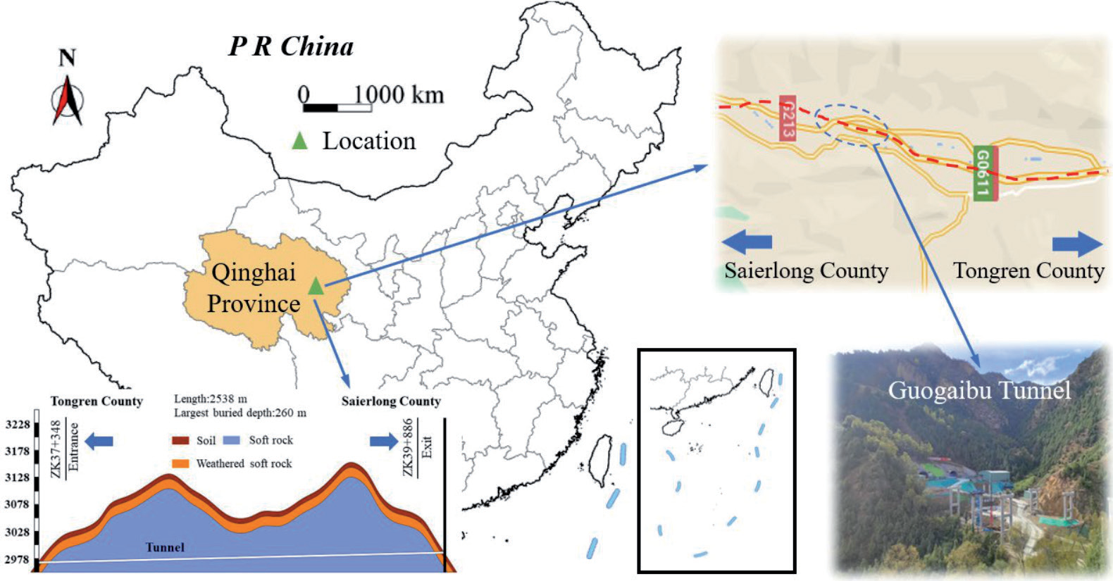
The Guogaibu Tunnel, which was located on the G0611 road, was constructed within Tongren County in Qinghai Province, as shown in Fig 1. It belongs to a separated long tunnel, and the length of the left tunnel was 2538 m, while the right tunnel measured 2528 m. The dimensions of the tunnel were a width of 10.25 m and a height of 5 m, with a design speed of 80 km/h and a maximum burial depth of 260 m. It belongs to the erosive landform effected by tectonic movement, and the strata were gravels, strongly weathered andesite, and moderately weathered andesite. The groundwater included quaternary loose layer pore water and fissure water. The rock mass was fragmented, and its strength and stability were poor, which could easily lead to the instability of the tunnel.
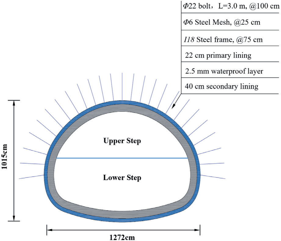
The composite lining, which included a primary support, waterproof layer, and secondary lining, was utilized in Guogaibu Tunnel construction with a two-step method, as shown in Fig. 2. In the primary lining, an I18 steel frame was used, which played a crucial role in reinforcing the structure. C25 shotcrete with a thickness of 22 cm was utilized, and the diameter of steel mesh was 6 mm with a circumferential spacing of 25 cm. The length of Bolt was 3 m with a diameter of 22 mm and 100 cm spacing. In the secondary lining, C35-reinforced concrete was utilized with a thickness of 40 cm.
The Process of Collapse
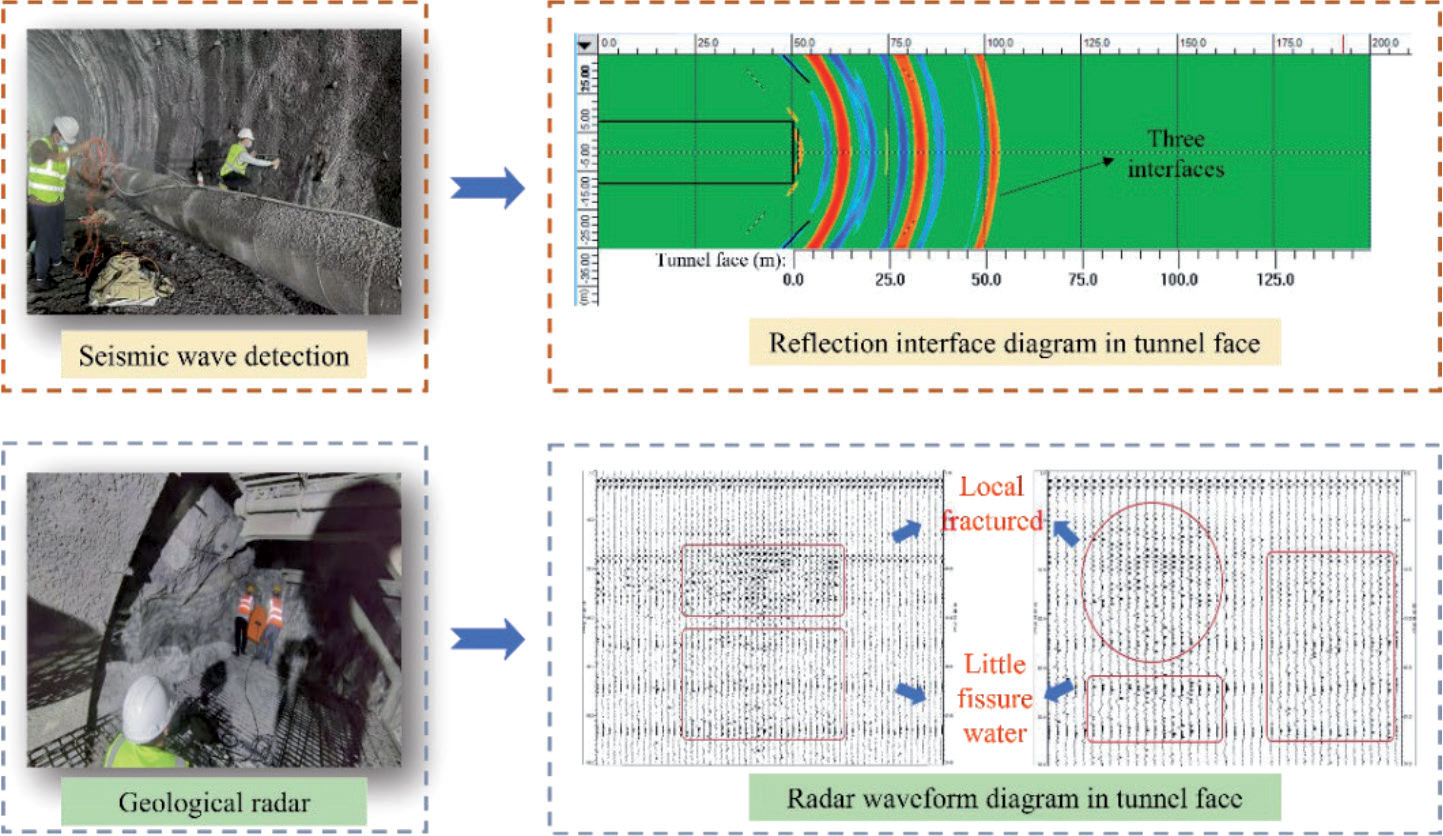
The advanced geological prediction was conducted in the ZK37+360 section by the seismic wave method and the GPR detection method, as shown in Fig. 3. In the seismic wave method, the overall effective length is about 100 m, and there were three interfaces 5-55 m ahead of the tunnel face. It revealed the development of joints and fissures in this area, and the stability of the weathered surrounding rock was notably compromised. In the GPR detection method, the electromagnetic wave signals had slightly staggered inphase axes and slight changes in amplitude at 16-27 m ahead of the tunnel face. It indicated that the surrounding rock was of poor integrity with local fragmentation and contained little fissure water, which could easily lead to disasters such as collapse or water inrush.
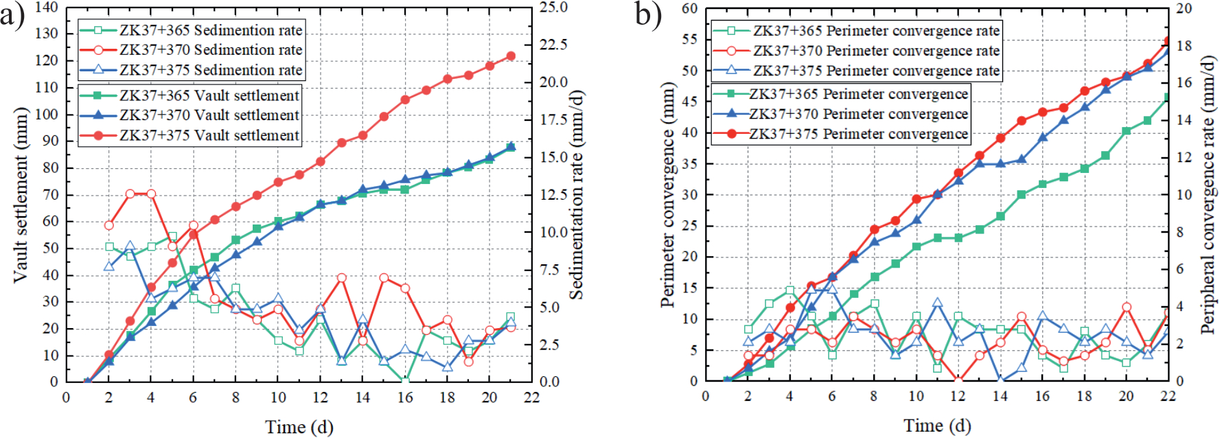
The data from the monitoring of displacement in sections ZK37+365, ZK37+370, and ZK37+375 is shown in Fig 4. Notably, both vault settlement and perimeter convergence exhibited a consistent increase without a converging trend. It reached its peak before the collapse. The largest vault settlement reached 122 mm, and the max vault settlement rate reached 12.6 mm/d. The max perimeter convergence reached 54.9 mm, and the max perimeter convergence rate reached 4.9 mm/d, which extremely exceeded the limits in the specification.
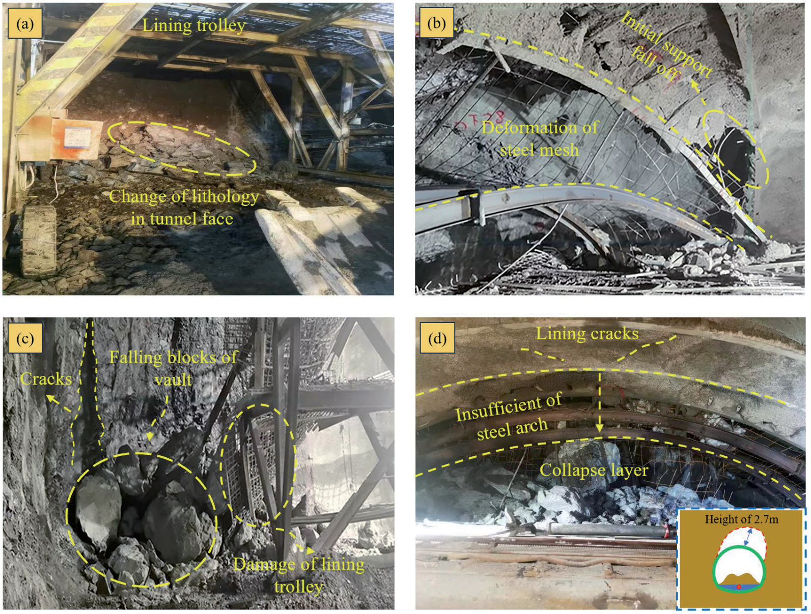
The burial depth of the entrance section in the Guogaibu tunnel was about 35 m, and the geological condition was extremely poor. During the construction, there was strong rainfall, and surface water entered the cracks into the surroundings. When the steel frame was constructed on the ZK37+380 section of the tunnel, cracks with a width of 1 m occurred in the initial support, where local falling blocks occurred (Fig 5c). In the meantime, rock loosening and sliding occurred on the right side of the arch joint fissure surface in ZK37+380-ZK37+385, and several transverse and longitudinal cracks also appeared (Fig 5b). Subsequently, the collapse of the tunnel vault continued to develop, and the right cutting surface was loose. The collapse area was in an elliptic shape with a height of 2.7 m and a width spanning 3 m. The longitudinal length was approximately 4 m. The initial support of the ZK37+378-ZK37+380 has already been damaged behind the tunnel face. The completed steel arch (without shotcrete) of the ZK37+380-ZK37+384 section was damaged, and the right working platform of the excavation trolley had large deformations.
Failure Mechanism of Collapse
Weathering of Rock Mass
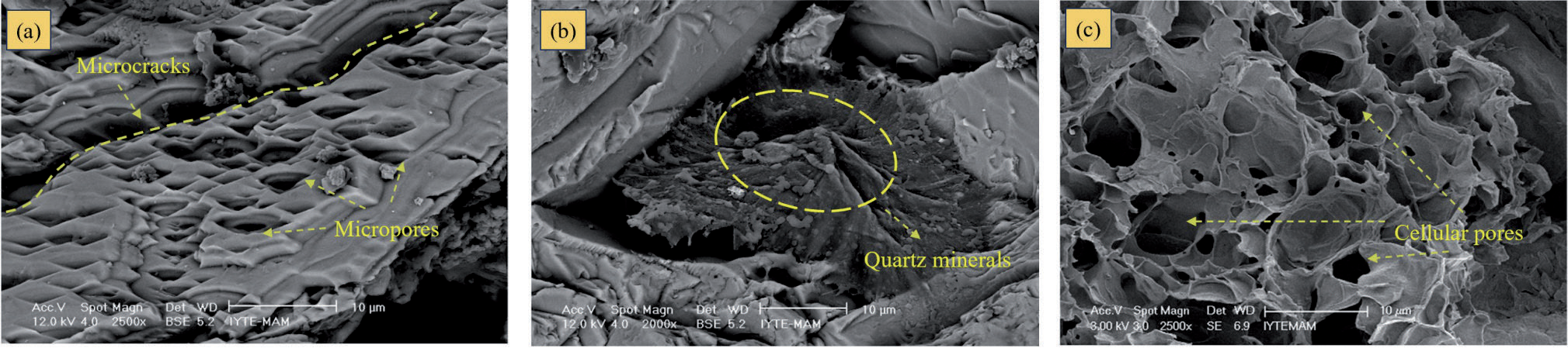
Under the weathering process of water, temperature, and atmosphere, the material composition and structure of andesite have changed, thereby altering its mechanical characteristics. To comprehend the compositions and microstructures of andesite and weathered andesite, laboratory analyses were conducted using XRD (X-ray diffraction) and SEM (Scanning Electron Microscope) [25, 26]. Andesite was primarily composed of silicon dioxide (SiO2), aluminum oxide (Al2O3), and iron oxide (Fe2O3), with smaller amounts of sodium oxide (Na2O), potassium oxide (K2O), magnesium oxide (MgO), and calcium oxide (CaO) [27]. The mineral composition of weathered andesite was mainly potassium feldspars, sodium feldspar, andesine, quartz minerals, etc. Higher magnification SEM was employed to discern the microstructural distinctions in weathered andesite, as shown in Fig. 6a). The density was 2.3-2.4 g/cm³, and the porosity was 7.7-8.2% in andesite. Affected by climate, temperature, and wet conditions, physical weathering is promoted [28, 29]. With the gas entering, the internal pores gradually formed. Finally, the density of the rock mass decreased to 2.0 g/cm³. In the meantime, porosity reached between 14.6% and 21.5% in the exterior weathered regions. In SEM images, it revealed the presence of microcracks and micropores extending from the surface to the inner part of the rock mass, which contributed to a reduction in strength and an increasing trend in deformability, as shown in Fig. 6c) [30].
Fig. 6.
Microscopic characteristics of weathered andesite: a) Void spaces images in BSE, b) Microstructure images in BSE, c) Weathered andesite image in SEM [27].
Deterioration of Groundwater
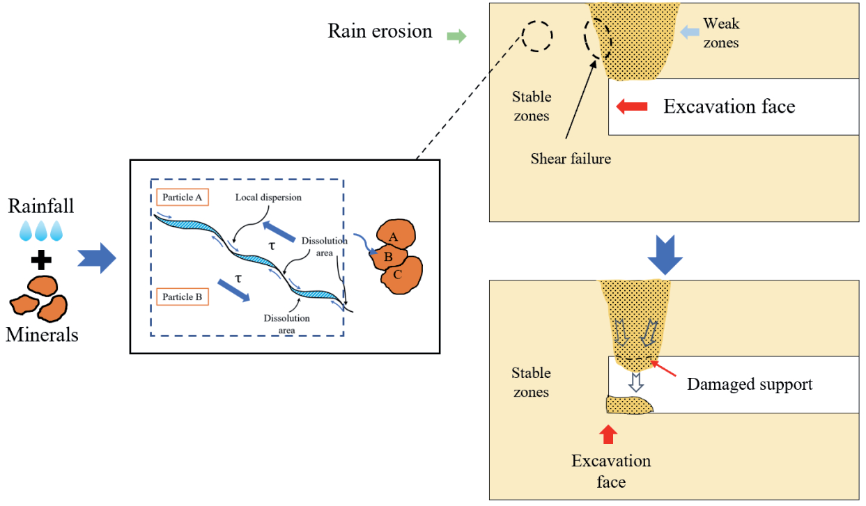
Due to the rainstorm, the groundwater could soften the weathered andesite through seepage. Microscopically, groundwater could have ion exchange with plagioclase feldspar. The clay minerals between rock structural planes are discretized, which could lead to secondary microcracks. During tunnel excavation, the microcracks expanded through stress redistribution, which could cause damage to the surrounding rock [31, 32]. Macroscopically, the mechanical characteristics of weathered andesite significantly deteriorated due to the combined influence of groundwater and stress fields [33- 35].
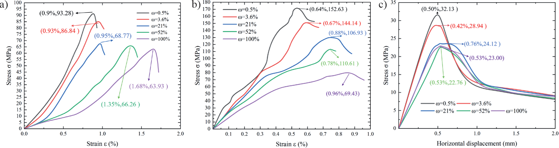
Laboratory experiments were conducted to explore the mechanical characteristics of weathered andesite under different saturations (0.5%, 3.6%, 21%, 52%, and 100%) at the tunnel site, which included uniaxial compression, triaxial compression, and direct shear tests. In lower water content, the weathered andesite displayed tensile shear failure features with approximately 0.9%- 0.95% strain, as shown in Fig. 7a). With the water content increasing, the toughness of the rock could also be enhanced. The saturated sample will fail at a strain of 1.68%, and the strength has significantly decreased by 31.46%. Simultaneously, the triaxial compression test and direct shear test were performed under a confining pressure of 10MPa. As shown in Fig. 7b), the peak strength of weathered andesite exhibited a noteworthy reduction with increasing saturation. Additionally, the rock entered the plastic stage before reaching its peak strength, and higher saturation accelerated deformation. Furthermore, a considerable decrease in the shear strength of weathered andesite with saturation increasing was demonstrated in Fig. 7c), with the shear strength notably lower than the compressive strength. After the peak points, the curve exhibited a rapid decline, reaching a residual strength. It found a substantial weakening effect of water on the mechanical properties of weathered andesite, particularly in shear strength.
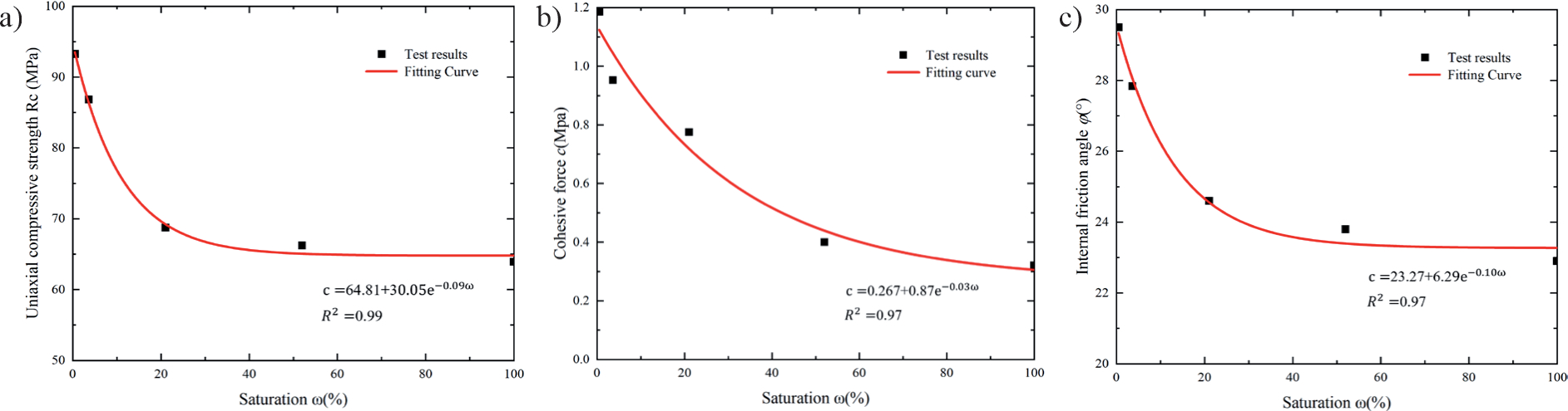
The characteristics and peak strength of weathered andesite are shown in Fig 8. In Fig. 8a), a substantial decline in uniaxial compressive strength was evident under low water content conditions, following an exponential curve pattern. It dropped from 93.28 MPa in the natural state to 68.77 MPa at 50% saturation, accounting for an 83.51% reduction in overall strength. However, the decrease was only 4.84 MPa when reaching full saturation (100%). In Figs. 8b) and 8c), there was also an exponential decay with increasing saturation. In cohesive force results, there was a 42.86% decrease in saturation from 0.5% to 21%, a 44.16% decrease from 21% to 52%, and a 12.98% decrease from 52% to 100%. Specifically, the internal friction angle decreased by 26.67% from 0.5% to 3.6% saturation but merely decreased by 0.05% from 52% to 100% saturation. It was found that the gradual dissolution of soluble minerals in weathered andesite led to a reduction in compressive strength and a significant decline in shear strength.
Insufficient Supporting
While constructing the Guogaibu Tunnel, there was a rainstorm at the tunnel site. The groundwater seeped into the tunnel vault, which resulted in an extra load in the surrounding area [36, 37]. It can also reduce the mechanical strength and increase the water pressure. In the two-step method, the larger excavation cross-section could make the support bear more loads. Even worse, the overlong footage, which exceeded 30 m between the upper bench and the tunnel invert, could make the primary lining unable to be closed timely. Subsequently, the rock in the tunnel vault started to loosen, leading to the collapse of the tunnel vault. Even with the application of larger I-beams, bending, deformation, and collapse still occur during construction, which indicated that the strength of the original support and construction method was insufficient in a weathered andesite tunnel.
Collapse Failure Mechanism
After excavation, the surrounding rock had a free state, and the normal force 𝜎𝑛 on the structural plane experienced a reduction. While the shear force 𝜏 increased, it was more prone to shear deformation. There was a stress concentration in rock mass after the stress redistribution in the surroundings, resulting in rising displacement in the normal direction of the structural plane. Consequently, there was a decrease in both the normal deformation stiffness and the shear stiffness of the structural plane. The instability critical point of the surrounding rock in the weathered andesite primarily relied on the shear strength of the structural plane, as indicated in the following formula proposed by Barton [38]:
JCS represents the compressive strength of the structural plane. 𝜑𝑏 represents the basic friction angle of the rock surface. JRC represents the roughness of the structural surface. 𝜏 represents the shear force. 𝜎𝑛 represents the normal stress. The collapse process in the excavation of the weathered andesite tunnel can be described in Fig 9. When the 𝜎𝑛 decreased after excavation, the shear strength of the structural plane also decreased. Weathered andesite had a weak structural plane with lower shear strength. The surrounding rock of the tunnel experienced shear sliding and tensile failure when surpassing the shear strength. Simultaneously, a continuous rainstorm led to a continuous increase in the internal water content of weathered andesite, which can also reduce the shear strength of the structural plane by crack propagation, advancing the critical point of overall instability in the surrounding rock [39]. In Fig. 3, it showed a rapid increase in vault settlement of the surrounding rock on the third day, which indicated a changing stress state in the surrounding rock. When excavating in the ZK37+380 section, continuous loosening caused some unstable rock blocks to collapse, increasing the load on the surroundings. Additionally, the initial support capacity was insufficient, and the construction method was unsuitable, resulting in the eventual collapse of the tunnel.
Optimization of Treatment
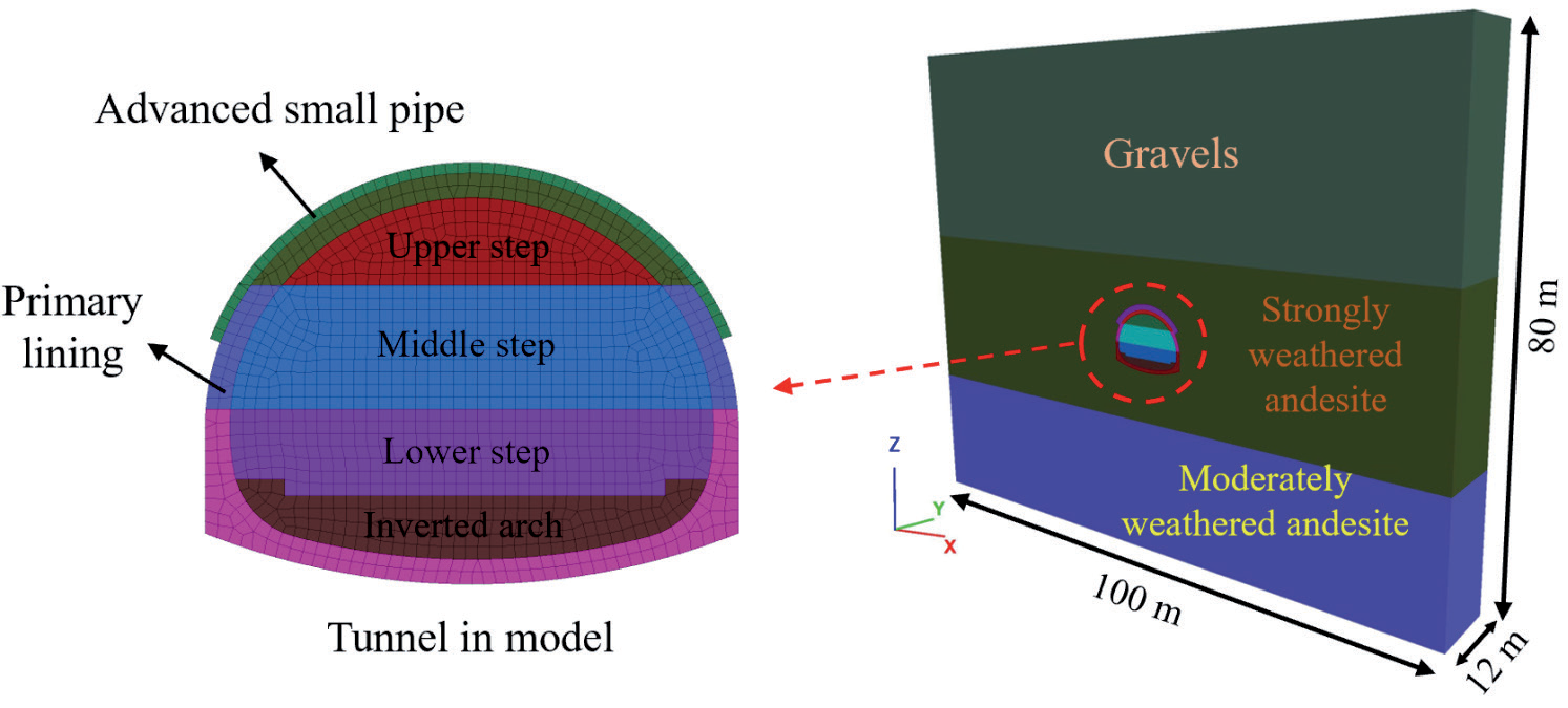
The FLAL 3D software was used to set up a numerical model to determine the parameters of advance support. The range of the model was taken as 3-5 times the tunnel diameter to prevent boundary effects [40]. The whole size of the model was 100 m × 80 m × 12 m, as shown in Fig. 10. The surrounding rock was modeled by the Mohr-Coulomb constitutive model, and the initial support was formed by the elastic constitutive model. The surrounding rock was assumed to be a continuous and uniform elastic-plastic medium. The solid elements and shell elements were used to simulate the primary lining and surrounding rock, respectively. The three-step method was used in tunnel excavation to prevent tunnel stability. According to the laboratory tests and field investigation, the mechanical perimeters of the surrounding rock and supports are shown in Table 1. The advanced small pipe was simulated by an elastic constitutive model. The equivalent value of the elastic modulus of the grouting area was calculated using the following formulas [41].
The parameters of the advanced small pipe reinforcement section in the surrounding rock would be more accurately determined. Based on the research and engineering experience, the four influencing factors were selected, such as the grouting area (A), the length of advanced small pipe (B), circumferential spacing (C), and the diameter of advanced small pipe (D). The parameters of grouting area included 105°, 120°, 135°, and 150°. The parameters of the length of the advanced small pipe included 3 m, 4 m, 5 m, and 6 m. The parameters of the length of circumferential spacing included 0.3 m, 0.4 m, 0.5 m, and 0.6 m. The parameters of the length of the diameter included 30 mm, 40 mm, 50 mm, and 60mm. A total of 16 orthogonal tests were carried out by using the L16 (44) orthogonal table.
Results and Discussion
The Results of Numerical Simulation
The vault settlement and perimeter convergence were recorded when excavation was completed, as shown in Table 2. Combined with the orthogonal test results and construction conditions, the parameters of the advanced small pipe were selected as 4 m in length and 50 mm in diameter. The grouting angle was 135°, and the circumferential spacing was 0.3 m. The numerical model in optimal condition was made to analyze the characteristics of the supports and surrounding rock.
Table 1.
Mechanical parameters in the Guogaibu Tunnel.
Table 2.
Results of the orthogonal test on the numerical simulation.
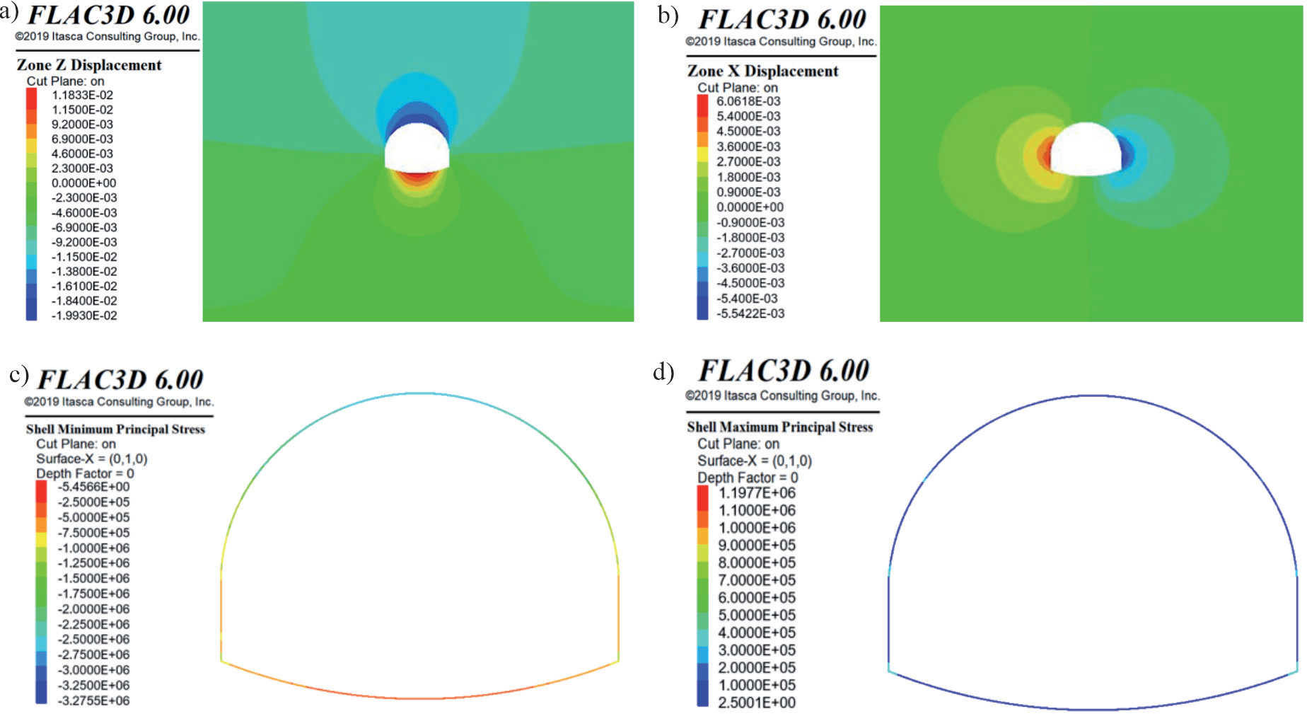
The total displacement and principal stress cloud map after tunnel excavation in the most dangerous section is shown in Fig. 11. In Figs. 11a) and 11b), it was indicated that the loose circle around the tunnel was larger in the surface direction. The settlement of the surrounding rock was relatively large in the strongly weathered andesite strata. The maximum settlement in the tunnel vault of the model was 19.93 mm, and the value of the inverted arch uplift was 11.83 mm. After excavation, the perimeter convergence had a trend of contraction with a maximum convergence value of 11.6 mm, which was small enough. The principal stress was important in evaluating the stability of the initial support, which could also research the influence of potential racking and failure in the initial support. In the FLAC 3D software, the negative minimum principal stress represented compressive stress, while the positive maximum principal stress represented tensile stress. In Figs. 11c) and 11d), the compressive stress on the initial support exhibited its highest values in the vault and spandrel of the tunnel. The maximum compressive stress reached 3.276 MPa in the tunnel vault, which was satisfied with the compressive strength requirement. In the meantime, the tensile stress on the initial support was most pronounced at the haunch and arch foot. The maximum tensile stress was 1.198 MPa in the arch foot area, which also met the tensile strength specification.
Treatment Measure
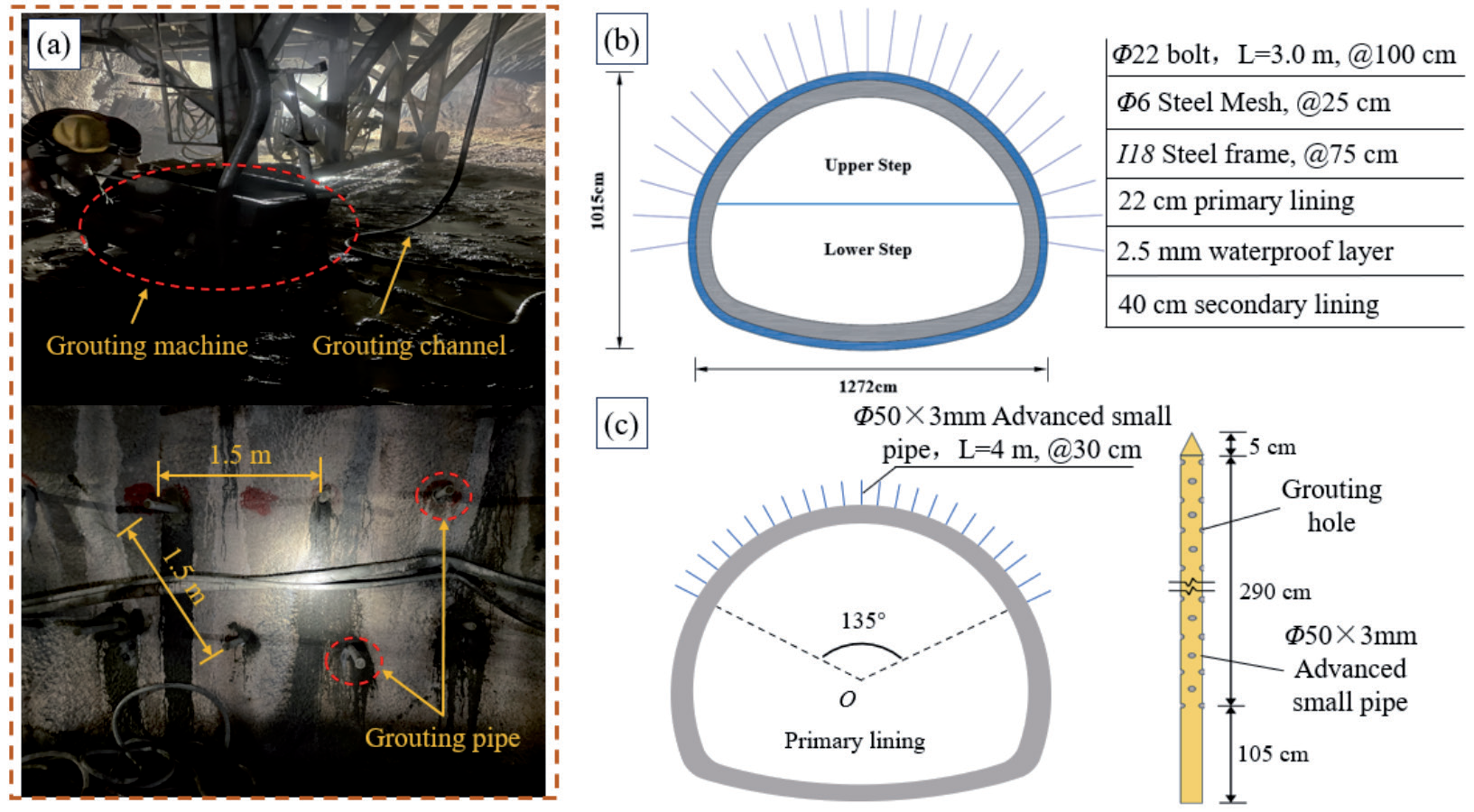
Under the influence of the collapse, the support has been damaged, and the surrounding rock has been completely disturbed. It needed to be grouted for reinforcement, as shown in Fig. 12a). The support in the tunnel face required higher strength to resist a potential secondary disaster. It adopted an I20a steel arch with a spacing of 60 cm and C25 shotcrete with a thickness of 26 cm in the primary support, while the secondary lining adopted C35 reinforced concrete with a thickness of 50 cm, as shown in Fig. 12b). In the ZK37+370-ZK37+420 section, it should be reinforced by advanced small pipe grouting to deal with poor geology in weathered andesite before excavation, as shown in Fig. 12c). The length of each pipe was 4 m, with a diameter of 50 mm and a circumferential spacing of 30 cm. The grouting area was 135°, and it was inserted into the surroundings at 15°. The advanced small pipe grouting procedure employed cement slurry with a water-cement ratio of 1.5:1, and the grouting pressure ranged from 0.6 to 1.2 MPa.
Treatment Evaluation
Monitoring After Treatment
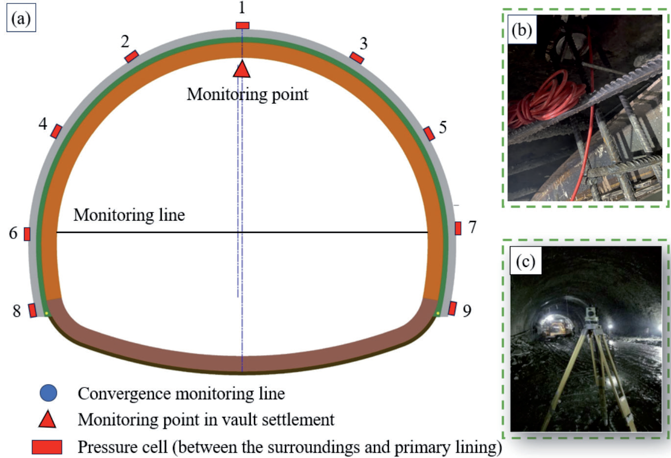
The ZK37+390 section near collapse was chosen to evaluate the treatment measure. The field test included vault settlement, perimeter convergence, and surrounding pressure. The arrangement of monitoring points and stress gauges is shown in Fig. 13. A total of 9 points were placed, including vault (1), left spandrel (2), right spandrel (3), left haunch (4), right haunch (5), left side wall (6), right side wall (7), left arch foot (8), and arch foot (9), as shown in Fig. 13a). The pressure cell was utilized to monitor the surrounding pressure in the primary support, as shown in Fig. 13b). In addition, the frequency of deformation monitoring was once a day in total 36d, as shown in Fig. 13c).
Result Analysis of Monitoring
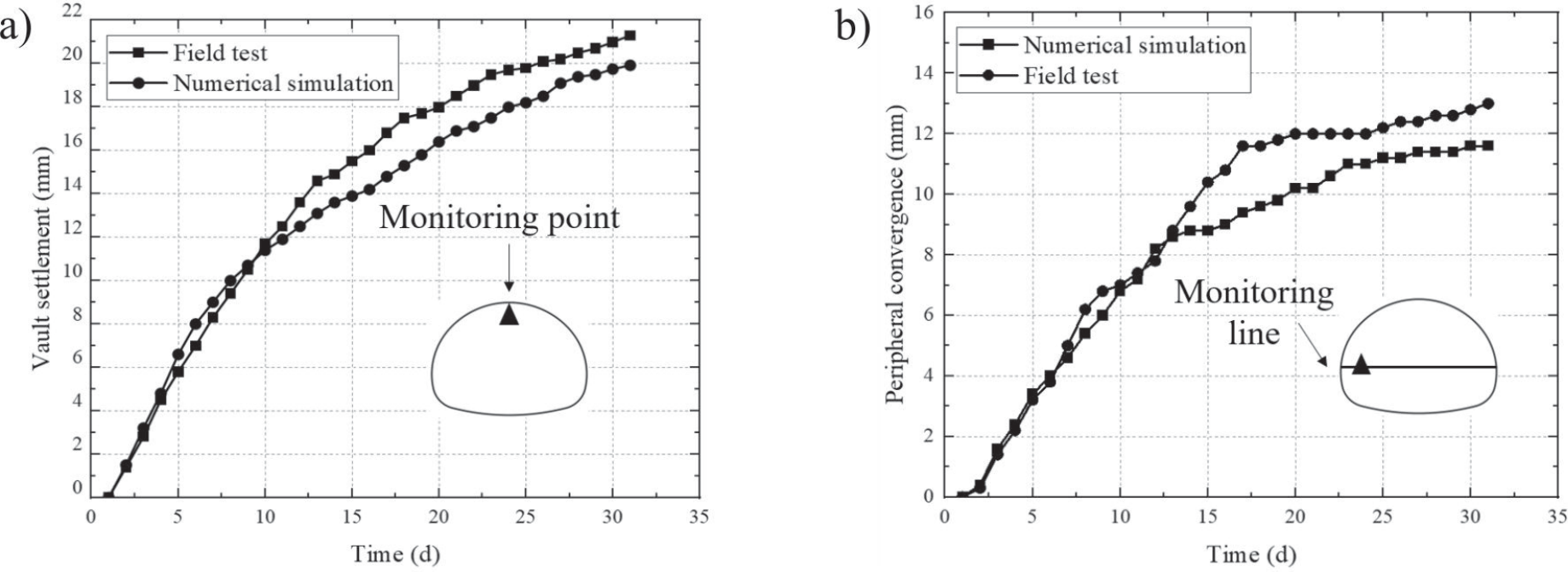
The monitoring results after excavation in ZK36+390 are shown in Fig. 14. The maximum vault settlement and maximum perimeter convergence in the tunnel were 19.93 mm and 11.6 mm, respectively, in the numerical simulation. Furthermore, the maximum vault settlement and perimeter convergence in on-site tunnel monitoring were 21.3 mm and 13.0 mm, respectively. The deformation trend of the tunnel in optimal condition was highly similar to the monitoring data. Due to the disturbances during the field construction, the measured data on site were slightly larger than the numerical simulations. The overall deformation was in the safe range.
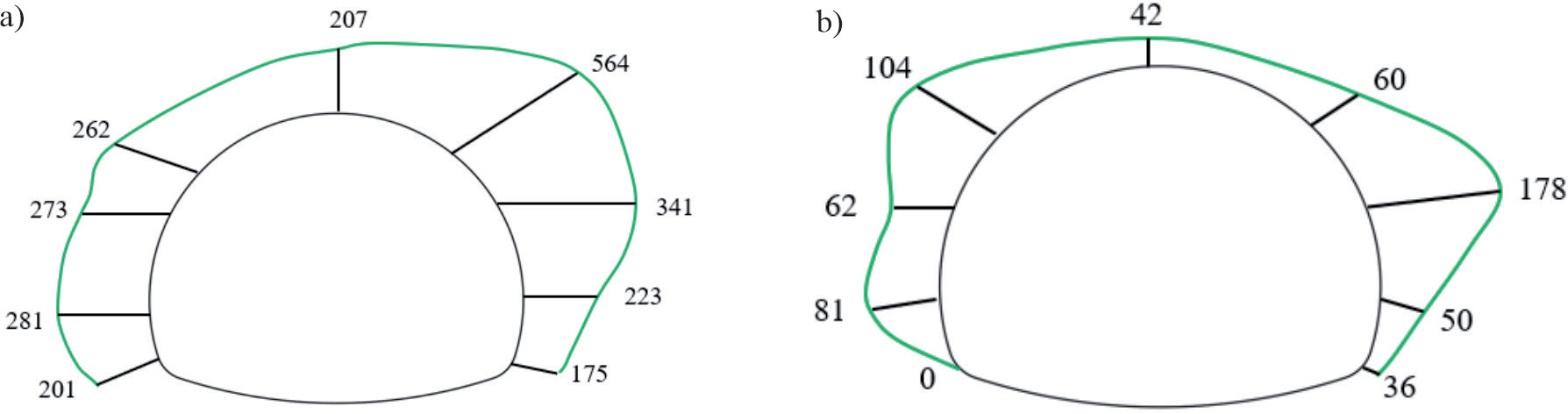
The surrounding pressure, specifically at ZK37+390 and ZK37+370, is shown in Fig. 15. The result of surrounding rock pressure after treatment was compared with it before collapse. After excavating the tunnel, there were no abnormal changes in the surrounding pressure, indicating the effectiveness of the treatment in enhancing stability within the tunnel in weathered andesite strata. After treatment, there was an overall decrease, and the most significant reduction was observed in the vault and arch feet. Specifically, the monitoring point in the right haunch exhibited the highest surrounding pressure at 178 kPa. Conversely, the surrounding pressure was measured at 42 kPa on the vault, much lower than that in the left spandrel. It indicated the efficacy of the treatment in reinforcing the strength of the surrounding rock. However, it was crucial to pay attention to the stress and deformation of the arch spandrel and haunch to prevent potential failure during construction.
Conclusions
In this article, we researched the failure characteristics and collapse failure modes of tunnels in weathered andesite strata. The investigation was conducted through a combination of laboratory tests and theoretical analysis. The treatment was put forward in combination with simulation and on-site conditions. The effect was investigated by on-site monitoring. The main conclusions are presented:
(1) When the steel frame was constructed on the ZK37+380 section of the tunnel, cracks with a width of 1 m occurred in the initial support, where local falling blocks occurred. Subsequently, the collapse of the tunnel vault continued to develop, and the right cutting surface was loose. The collapse area was in an elliptic shape with a height of 2.7 m and a width spanning 3 m. The longitudinal length was approximately 4 m. The initial support of the ZK37+378-ZK37+380 has already been damaged behind the tunnel face.
(2) The internal microcracks of andesite formed in the weathering process, and the strength decreased. With saturation increasing, the minerals in the structural plane of weathered andesite gradually dissolve under the action of seepage, leading to the expansion of microcracks. Macroscopically, the strength of the surrounding rock was further reduced, especially in shear strength. When the shear strength decreased to the ultimate strength, leading to the occurrence of collapse accidents.
(3) To prevent a secondary disaster, strengthening support and advanced small pipe were used in tunnel construction. The specific parameters of the advanced small pipe were determined through numerical simulation. The strength of the surrounding rock and support has been strengthened. The treatment was effective based on the on-site monitoring results. It provides a reference for the prevention and control of tunnel crossings with weathered andesite strata.