


Introduction
Blast and open-hearth furnaces are well-known primary consumers of natural gas in the metallurgical industry. Blast furnaces use natural gas as a process raw material as a reducing agent, thereby partially reducing coke consumption. High-temperature processes underlie the production of ferrous metals. The heat costs associated with the metal production processes in the corresponding industrial furnaces are covered mainly by burning gaseous fuels. When fuel is burned, its latent chemical heat is released and converted into physical thermal energy, the carriers of which are combustion products heated to a high temperature [1]. Thermal energy from the flame and heated combustion products is transferred by convection, radiation, and contact. Heat is best transferred by radiation. Therefore, the torch luminosity is a determining factor in the process of fuel combustion [1].
In general, an industrial furnace consists of the following elements: – burners in which the gas is partially or completely
mixed with air and prepared for combustion; – furnaces in which fuel is burned; – the working space of the furnace, in which the main
work of the furnace takes place - the heat treatment
of the corresponding material; – disposing device (regenerator, recuperator or cooling
boiler); – a smoke exhauster, with the help of which fuel
combustion products are evacuated from the furnace,
and a chimney for their release into the atmosphere
and harmless dispersion.
Gas communications of workshops - gas consumers start from the general plant gas pipeline and end with a unit in which gas is burned. Gas communications include: a gas pipeline – a branch to the workshop with a common shut-off valve and other fittings, gas metering and control devices, including gas control points (hereinafter – GCPs) of natural gas, gas pipelines-collectors at each furnace, gas pipeline distribution to heating zones, including fittings installed on them and the burners themselves. As a rule, auxiliary devices of the gas economy include ventilation systems that provide air supply to the furnace when the unit is equipped with two-wire burners [1, 2].
The safety rules for metallurgical and coke-chemical enterprises and production plants in the gas sector apply to the designed, those under construction, reconstructed and operating gas facilities of metallurgical and coke-chemical enterprises and production plants, to energy facilities associated with the preparation, transportation and consumption of blast furnace, coke, converter, ferroalloy, natural gas, as well as their mixtures with an excess pressure of not more than 1.2 MPa and liquefied hydrocarbon gas with an excess pressure of not more than 1.6 MPa, used as fuel [1]. Design, construction, and reconstruction of gas facilities of metallurgical and coke-chemical enterprises and production plants shall be carried out in accordance with the current building codes and regulations, technological design standards, the requirements of general safety rules for enterprises and organizations of the metallurgical industry, the rules for the construction and safe operation of technological pipelines and other regulations [2-12]. Gas at a metallurgical production plant is distributed through GCPs.
To date, in the territory of the Russian Federation and the CIS countries, the absence of a single approved methodology for conducting visual and measurement quality control of GCPs has been revealed. The absence of a unified methodology does not allow to quickly make a decision on the correct technology for assembling and welding a structural element, as well as subsequently prevent accidents and emergencies [13-21], in turn, the requirements for the quality of structures and tracking emergency and emergency situations are provided for by safety rules in the gas facilities of metallurgical and coke-chemical enterprises and production plants [22].
The object of the research in this article is the activities and procedures performed in the preparation and conduct of visual and measurement control of GCPs at metallurgical and coke-chemical enterprises.
The purpose of the article is to analyze problematic issues in the preparation and conduct of visual and measurement quality control of welded joints of GCPs.
To achieve this goal, it is necessary to solve the following tasks:
1. To analyze regulatory legal acts and regulatory documents defining the procedure for preparing and conducting visual and measurement quality control of welded joints of GCPs;
2. Identify problematic issues that arise during the preparation and conduct of visual and measurement quality control of welded joints of GCPs;
3. Define a task for further investigation and elimination of identified issues on conduct of visual and measurement quality control of welded joints of GCPs
Hypotheses
General Information About Gas Control Points
A GCP is a complex of technological equipment and devices designed to lower the inlet gas pressure to a predetermined level and maintain it constant at the outlet. Depending on the location of the equipment, gas control points are divided into several types: – a Gas Distribution Plant (GDP), in which process
equipment is placed in a cabinet made of fireproof
materials; – a Gas Control Unit (GCU), in which the process
equipment does not provide for the presence of its
own enclosing structures, is mounted on a frame and
placed in open areas under a canopy, inside the room
in which the gas-using equipment is located, or in
the room connected to it by an open opening; – a Block-type Gas Control Unit (BGCU), in which
the process equipment is installed in one or more
transportable container-type buildings; – a Stationary Gas Control Point (SGCP), where
process equipment is located in buildings, premises
or open areas specially designed for this purpose.
The fundamental difference between GCPs and GDP, GCU and BGCU is that GCP (unlike the latter) is not a typical product of full factory readiness [23].
Design and Principle of Operation of a Gas Control Point
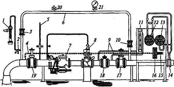
The schematic diagram of a GCP is shown in Fig. 1 [24]. Depending on the gas pressure at the inlet, they are divided into GCPs and GCUs of medium pressure (over 0.005 to 0.3 MPa) and GCPs and GCUs of high pressure (over 0.3 to 1.2 MPa). Since their principal technological schemes are similar, we will continue to use the term “GCP(s)” [25, 26].
A GCP is a complex of process equipment, devices and a technological process implemented on them in accordance with the relevant regulations; therefore, they are complex technological objects.
Confirmation of Compliance of Gas Regulatory Items with the Requirements of the Legislation of the Russian Federation and CIS Countries
Equipment, including agricultural, industrial and medical, is subject to mandatory assessment and verification of its compliance with safety requirements. Mandatory certification of equipment is a process of confirming compliance with the requirements stipulated by the applicable standards, rules and regulations, as well as the current technical regulations. Certification of equipment on a mandatory basis is required for all types of household (household appliances), food, heating, metalworking, radio-electronic, woodworking equipment, as well as hot water supply devices, etc. Equipment certification takes one of the main roles in the general flow of product certification in the Russian Federation and the CIS countries. Domestic manufacturers modernize enterprises and offer new solutions to existing problems, increase the functionality of structures, and increase production capacities.
GCPs are subject to mandatory assessment and verification of compliance with safety requirements.
GCPs are included in the list of products Decision of the EEC Board dated January 16, 2018 No. 6 On approval of the list of products in respect of which the filing of a customs declaration is accompanied by the submission of a conformity assessment document (information on the conformity assessment document) with the requirements of the technical regulation of the Customs Union “On the safety of machines and equipment” (TR CU 010/2011)” and belongs to the product group “Oilfield equipment, drilling exploration” and “Machinery and equipment for public utilities” [27].
Component parts of GCPs are subject to mandatory certification or declaration, in accordance with the requirements of the Technical Regulations of the Customs Union TR CU 010/2011, which regulates the safety of machinery and equipment, according to the List of Products [28] and TR CU 032/2013, for equipment and elements of equipment operating under excessive pressure, according to the List of products and in accordance with Annex No. 1 to the technical regulation of the Customs Union “On the safety of equipment operating under excessive pressure”, according to tables No. 6 and 7 defining the categories of pipelines and fittings intended for compressed, liquefied, dissolved gases under pressure and vapors and used for working environments of group 1 or 2 [29].
GCPs are also subject to conformity assessment of technical devices and equipment for compliance with federal norms and rules in the field of industrial safety, unless another form of conformity assessment is established by the technical regulation [30].
Fig. 1.
Schematic diagram of a GCP [24]. 1 – safety relief valve; 2 – relief valve lever; 3 – bypass valve; 4 – final pressure impulse tube; 5 – gas vent; 6 – bypass line (bypass); 7 – pressure regulator; 8 – safety shut-off valve; 9 – impulse tubes before and after the filter; 10 – valve on the bypass; 11 – differential pressure gauge for measuring the pressure drop across the filter; 12 – flow meter; 13 – registering inlet pressure gauge; 14 – diaphragm; 15 – indicating output pressure gauge; 16 – registering output pressure gauge; 17 – inlet valve; 18 – filter; 19 – outlet valve; 20 – purge pipeline with a valve; 21 – pressure gauge on bypass.
Only new equipment that has not been in operation is subject to mandatory certification or declaration, and equipment put into operation is subject to industrial safety assessment, including for extending its service life.
Technical regulations contain a requirement to ensure the safety of equipment during development, manufacture and production:
1. According to paragraph 2 of Article 5 of TR CU 010/2011, when manufacturing a machine and (or) equipment, the manufacturer shall comply with the entire range of safety measures specified in the design documentation, while it shall be possible to control the implementation of all technological operations that affect safety [27].
2. According to paragraph 8 of Article 4 of TR CU 032/2013, in order to determine the risks for equipment, factors representing the following main types of hazard should be taken into account: unacceptable deviations of design parameters, assembly units and safety devices that affect safety and damage associated with the deposition of impurities in the working environment on the internal surfaces of equipment elements [29].
Technical regulations contain requirements for the applicant to provide a set of documents containing: technological regulations and information about the technological process (data on the materials used, semi-finished products, components, welding materials, on the methods and parameters of welding modes and heat treatment, methods and results of non-destructive testing); information about the carried out tests (measurements); equipment test reports carried out by the manufacturer [26, 29]. The Visual and Dimensional Inspection (VDI) of GCPs is carried out in accordance with the requirements of interstate standards, and in case of their absence (before the adoption of interstate standards) - national (state) standards of the Member States of the Customs Union, as a result of which, on a voluntary basis, compliance with the requirements of the technical regulation of the Customs Union, and standards containing the rules and methods of inspection (testing) and measurements [29, 30].
GCPs are classified as hazardous production facilities, therefore they are subject to an examination of the industrial safety of gas pipelines, technical and technological devices of gas distribution networks and gas consumption is carried out in order to determine and predict their technical condition in accordance with Federal Law FZ-116 “On Industrial Safety of Hazardous Production Facilities” [30].
Industrial safety assessment is carried out in accordance with the procedure established by federal norms and rules in the field of industrial safety, based on the principles of independence, objectivity, comprehensiveness and completeness of research conducted using modern achievements in science and technology [30]. An industrial safety declaration is developed as part of the design documentation for the construction, reconstruction of a hazardous production facility, as well as documentation for the technical re-equipment, conservation, liquidation of a hazardous production facility.
The assessment of compliance with the requirements of TR CU and industrial safety assessment of gas control points are interrelated procedures. One of the stages of assessing the compliance of gas control points with the requirements of TR CU and industrial safety assessment is the visit of an expert to the facility and technical diagnostics of equipment using visual and measurement control methods in the volume required by regulatory technical documentation.
Materials and Methods
Visual and Measuring Control. Requirements for Measurement Instruments
Non-destructive testing by visual and measuring method is intended for:
– visual control of the base material, welded joints, overlays, etc.;
– measuring the shape and dimensions of products and welded joints, angular and linear values of semi-finished products, parts, assembly units, welded joints, products, as well as surface defects;
– measuring structural elements, shape and dimensions of edges, gaps of joints assembled for welding, as well as dimensions of completed welds;
– technical diagnostics during the operation of products in accordance with the requirements of drawings, regulatory and technical documents.
VDI is one of the main methods of non-destructive testing. Without visual and measuring control, it is inappropriate to proceed to control by other methods and further testing of equipment.
The means of control during the VIC must be in good order, configured and verified in the prescribed manner. The means of control shall also have an instruction manual, an operating manual and a verification certificate [31].
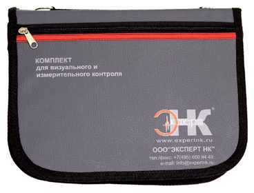
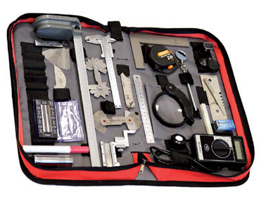
In the public domain, you can purchase a universal flaw detector kit that fully complies with the requirements of STO 9701105632-003-2021. This document was adopted on March 25, 2021, and is the current revision of RD 03-606-03 “Instruction for visual and measurement control”, put into effect by order of the Federal Mining and Industrial Supervision of Russia dated July 17, 2003, No. 156, which is no longer valid from January 01, 2021 [32, 33]. This document was included in the list of repealed regulatory legal acts of the federal executive authorities (Decree of the Government of the Russian Federation of August 6, 2020, No. No.1192). An example of such a set is shown in Figs 2, 3.
For visual and measuring control, the following are used:
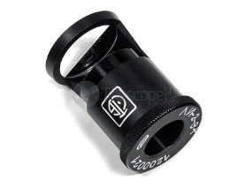
– visual-optical devices up to 20x magnification (magnifiers, including measuring ones, endoscopes, mirrors, etc., according to figures 4-6);
– line measures of length (steel measuring rulers in accordance with GOST 427-75 “Measuring metal rulers. Technical Specifications”, tape measures in accordance with GOST 7502-98 “Measuring metal tapes. Technical Specifications”, according to Figs 7, 8).
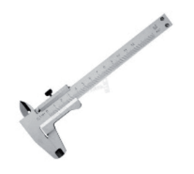
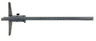
– calipers (calipers according to GOST 166-89- “Calipers. Technical Specifications” and depth gauges in accordance with GOST 162-90 “Depth gauges. Technical Specifications, according to Figs 1.12, 1.13);
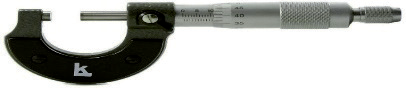
– micrometric devices (micrometers according to GOST 6507-90 “Micrometers. Technical Specifications”, according to Fig. 11);
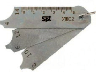
– templates, including special and universal ones (for example, welder’s gauge, templates for measuring the radius, etc., according to Figs 12-13).
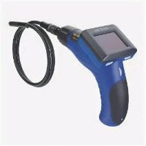
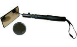
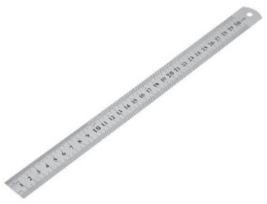
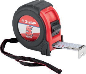
It is permitted to use other means of visual and measuring control, subject to the availability of appropriate instructions and methods for their use.
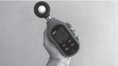
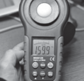
To create an optimal contrast of the defect with the background in the control zone, it is necessary to use an additional portable light source, i.e. use combined lighting. Illumination of controlled surfaces should be sufficient for reliable detection of defects, but not less than 500 lx. A light meter is a specialized device that allows you to measure the parameters of the actual illumination in the surrounding space. There are many varieties of this device, each of them is sensitive to certain spectral radiation and has its own permissible error. A normal error is considered to be a deviation of no more than 3-4%, while there are models with a tolerance of 7-10%. This is not so important, since the accuracy of the illumination measurement often depends on the angle of the light and other factors. There are a large number of types of light meters; examples are shown in Figs 14-16.

Permissible measurement error during visual and measurement control in accordance with the requirements of STO 9701105632-003-2021 are presented in Table 1.
Measuring instruments and tools for visual and measuring control must periodically, as well as after repair, undergo verification (calibration) in metrological services accredited in the prescribed manner. The term for verification (calibration) is established by Normative Documentation (ND) for the relevant tools and instruments [29].
Main Rejection Criteria
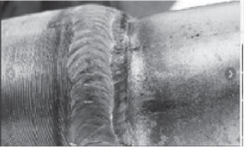
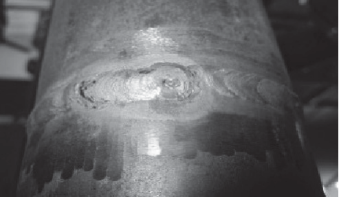
The main rejection criteria to which special attention should be paid during visual inspection are:
1. The discrepancy between the geometric dimensions of the weld is excessive or insufficient force, uneven width of the seam [25];
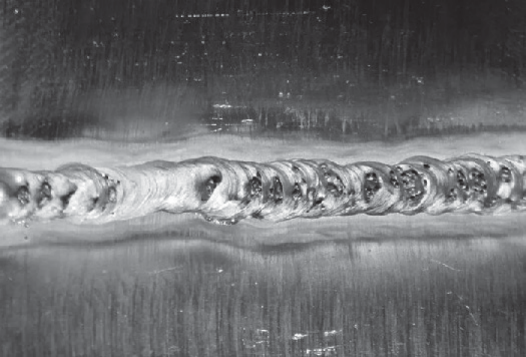
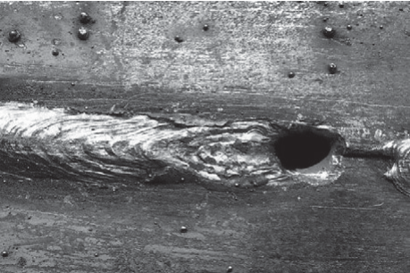
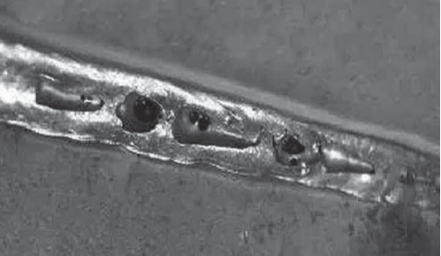
2. A pore in a weld is a weld defect in the form of a round-shaped cavity filled with gas, Fig. 17;
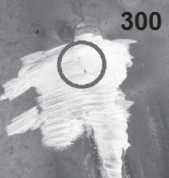
3. Inclusions – Foreign particles reduce the strength of the seam and act as places of localization of excessive stresses, Fig. 18.
4. Unwelded craters are a defect in the weld, which is formed in the form of depressions in places where the arc abruptly breaks off at the end of welding. Shrinkage friability may appear in the depressions of the crater, often turning into cracks, Fig. 19.
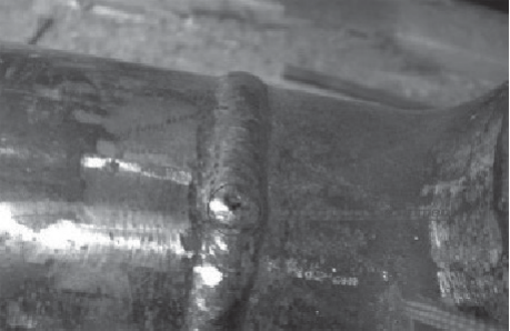
5. Burn-through – through penetration, accompanied by the outflow of liquid metal from the wrong side of the seam being performed, Fig. 20.
6. Fistulas – a defect in the form of a tubular cavity in the weld metal formed due to gas emissions during the welding process, Fig. 21.
7. Shrinkage cavities are a defect in the form of a cavity or depression formed during the shrinkage of the weld metal in the absence of liquid metal supply, Fig. 22.
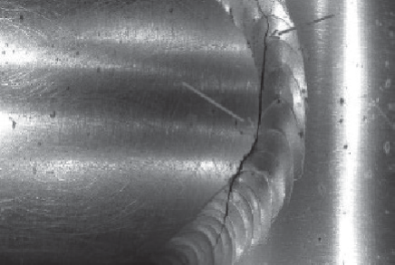
8. Cracks – a defect in a welded joint in the form of a gap in the weld and (or) areas adjacent to it, or – a discontinuity caused by a local rupture of the weld, which may occur as a result of cooling or the action of loads, Fig. 23.
9. Edge offset – incorrect position of the welded edges relative to each other (mismatch between the levels of the location of the welded parts in butt welded joints),
10. Ovality: Violation of the shape of the cross-section of the pipe (bend), characterized by its deviation from the ideal annular.

A rejection criterion is a set of parameter values and other features sufficient to assess the technical condition of an object and classify it as having certain defects. The observed indicators of the transition of an object from one technical state to another are the limiting values of diagnostic parameters.
When determining the possibility of operating the control object, the rejection criteria shall be classified into:
The classification takes into account the nature, size, location of rejection criteria for parts, features of parts and products, their purpose, conditions of use.
Visual and measurement control shall be carried out on all accessible surfaces of pipelines, parts, assembly units, GCPs’ equipment.
VDI is performed before the control of materials and welded joints by other methods of control and other tests at all stages of a GCP life cycle.
Results and Discussion
When working on the article, the following regulatory documents on visual and measuring control of the technical condition of GCPs were studied a lot of regulatory documents [21].
Since a large number of GCPs are used by GAZPROM Open Joint Stock Company, an internal document was developed within the organization for conducting VDI of GCPs and rejecting circumferential welded joints of gas distribution pipelines – STO Gazprom 2-2.3-626-2011 “Gas Distribution Systems Criteria for Rejecting Circumferential Welded Joints of Gas Distribution Pipelines”, this service station is also used by other organizations as a regulatory document for visual and measuring control of gas control points. Along with STO Gazprom 2-2.3-626-2011, SP 42-102-2004 “Design and Construction of Gas Pipelines from Metal Pipes” and the Methodology for conducting an industrial safety assessment and determining the period of further operation of gas equipment of industrial furnaces, boilers, GCPs, GCU, GDP and steel gas pipelines, approved by the General Director of “SEC Industrial Safety” NPO, A.A. Sorokin, while the safety requirements, including the rejection criteria of these documents are different.
Table 2.
Comparison of criteria for rejection of girth welded joints of steel distribution gas pipelines based on the results of visual and measurement control in the analysis of STO Gazprom 2-2.3-626-2011, SP 42-102-2004, Methods for conducting industrial safety assessment, approved by A.A. Sorokin.
Comparison of criteria for rejection of girth welded joints of steel distribution gas pipelines based on the results of visual and measurement control in the analysis of STO Gazprom 2-2.3-626-2011, SP 42-102-2004 and the Methodology for conducting an industrial safety review approved by A.A. Sorokin are presented in Table 2 [34, 35].
Conclusions
During the study, an analysis of problematic issues was carried out during the preparation and conduct of visual and measurement quality control of welded joints of GCPs, and the following tasks were solved:
1. The analysis of normative documentation on visual and measurement quality control of welded joints of GCPs was carried out.
2. When analyzing the regulatory documentation for conducting visual and measurement quality control of welded joints of GCPs, it was revealed that there is no single approved methodology for conducting visual and measurement quality control of welded joints of GCPs at all stages of the life cycle of a complex technological object.
3. The task is set to further develop a unified methodology for conducting visual and measurement quality control of welded joints of GCPs.